
Card swipe system with data protection

A technology of data protection and card swiping system, applied in the direction of processing coins or valuable banknotes, coin-free or similar appliances, and the activation of coded identification cards or credit cards, etc. Protective device protection mechanism, card swiping or tampering, etc., to achieve the effect of improving data protection

Active Publication Date: 2019-01-15
MITAC COMP (SHUN DE) LTD +1
View PDF7 Cites 0 Cited by
  • Summary
  • Abstract
  • Description
  • Claims
  • Application Information

AI Technical Summary

Problems solved by technology

However, the common method of hacking is to invade the magnetic card reading unit, such as: hacking the magnetic card reading unit to connect the internal signal transmission circuit, etc., resulting in the confidential data of the card being stolen during the card swiping transaction process.
Although there is a detection and protection circuit added to the signal transmission circuit of the magnetic card reading unit, when an external force tampers with the internal signal transmission circuit of the link, it will cause the detection and protection circuit itself to form an open circuit or cause the detection and protection circuit to be disconnected from the power supply. The protection mechanism that the circuit or other signal lines are short-circuited to trigger and activate the safety protection device
However, the current detection and protection circuit has a relatively simple structure and is easily bridged by tampering. Once the detection and protection circuit is tampered with and bridged, the detection and protection circuit itself will not form an open circuit or the detection and protection circuit will not be connected to the bridge. A short circuit in the power circuit or other signal lines will not be able to trigger the protection mechanism of the safety protection device, resulting in hazards such as skimming or tampering of swiping cards

Method used


Image

  • Card swipe system with data protection
  • Card swipe system with data protection

Examples


Embodiment Construction

[0013] Before the present invention is described in detail, it should be noted that in the following description, similar components are denoted by the same numerals.

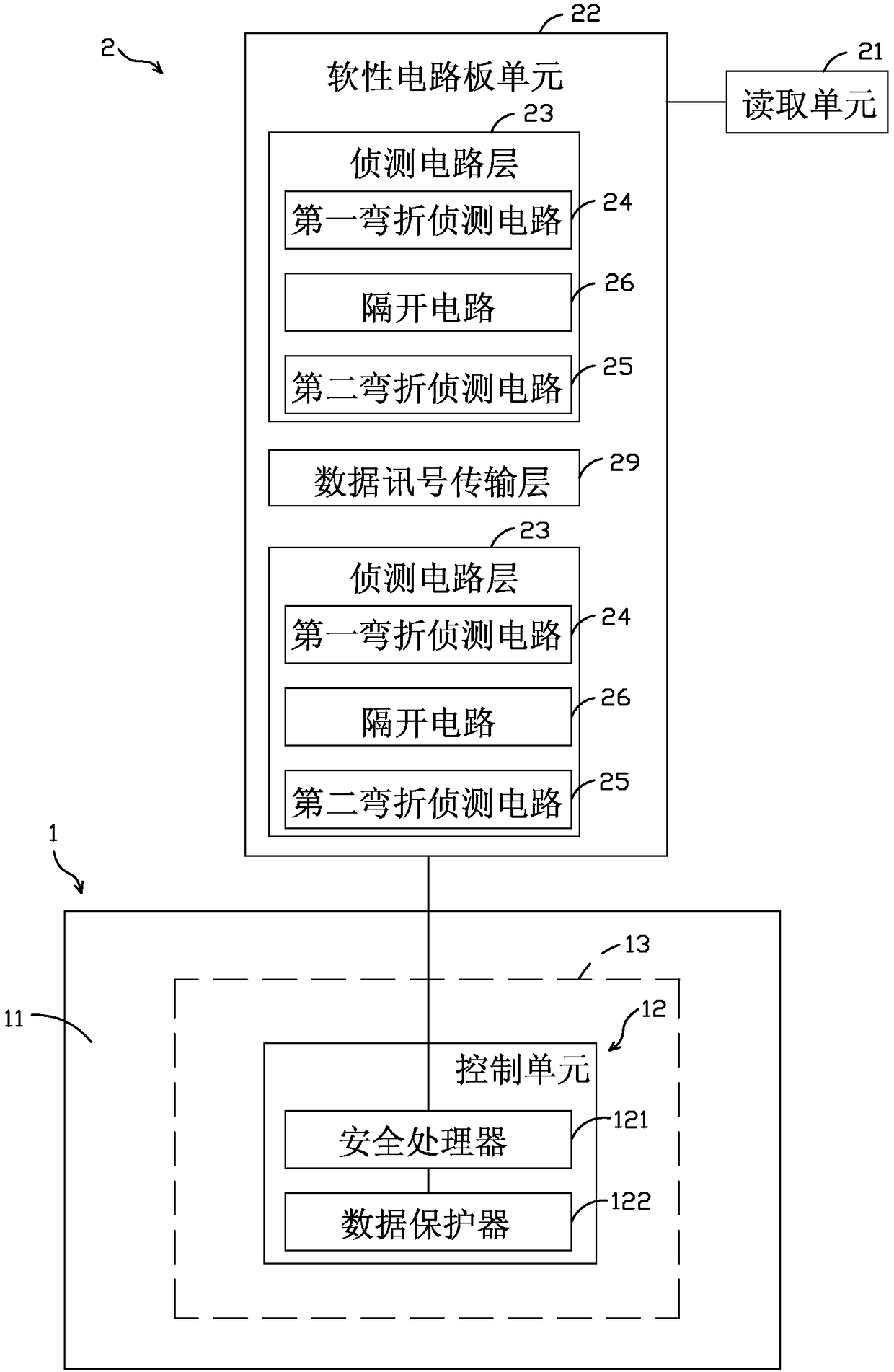
[0014] refer to figure 1 and figure 2 , The card swiping system with data protection function of the present invention includes a security processing device 1 and a reading device 2 linked to the security processing device 1 .

[0015] The security processing device 1 includes a main board 11 , a control unit 12 arranged on the main board 11 , and a protection unit 13 arranged on the main board 11 and covering the control unit 12 . The control unit 12 includes a security processor 121 and a data protector 122 connected to the security processor 121 .

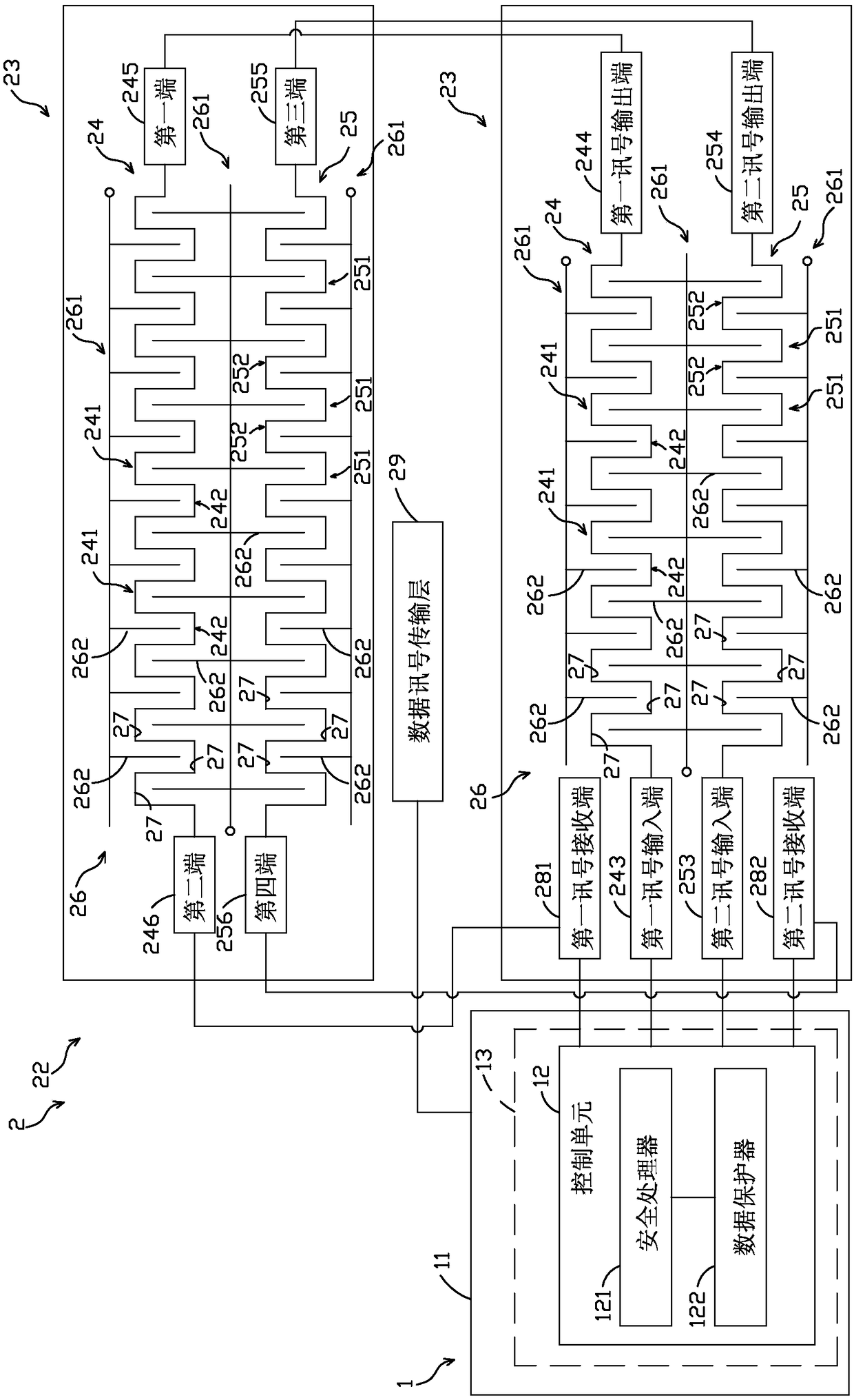
[0016] The reading device 2 includes a card reading unit 21 (Magnetic Swipe card reader, MSR), and a flexible circuit board unit 22 connecting the card reading unit 21 and the control unit 12 . The flexible circuit board unit 22 has two detection circuit laye...


PUM


Abstract

A card swipe system with data protection function, comprising a security processing device and a reading device linked to the security processing device. The security processing device includes a control unit. The reading device includes a flexible circuit board unit coupled to the control unit. The flexible circuit board unit has two detection circuit layers. Each detection circuit layer has a first bending detection circuit for transmitting a first signal, a second bending detection circuit for transmitting a second signal, and a separate circuit for transmitting a third signal. The first bending detection circuit and the second bending detection circuit respectively form a plurality of bending intervals. The separate circuit has a plurality of branch line portions extending between thecorresponding bending intervals. Thereby, the branch line portion effectively separates the two or two spaced and adjacent bend portion in the first and second bending detection circuits, so that thebend portion cannot be easily bridged by an external bridge, effectively improving data protection.

Description

technical field [0001] The invention relates to a card swiping system for financial payment, in particular to a card swiping system with data protection function. Background technique [0002] POS machines, which are commonly used in financial transactions today, are convenient for consumers to swipe their cards to pay the amount. However, the confidential data such as the swiped card data, the input password and the amount during the transaction must be protected to prevent the swiped card data from being skimmed, stolen or tampered with. harm. [0003] Generally speaking, the POS machine uses its magnetic card reading unit (Magnetic Swipe card reader, MSR) to swipe the card, and obtains the card information and cooperates with the internal signal transmission circuit to transmit the card information to the security protection device (Security box) of the POS machine. ) to perform follow-up transaction operations, such as: card acquisition of remote bank authorization auth...

Claims


Application Information

Patent Timeline
IPC IPC(8): G07F7/08G07G1/12
CPCG07F7/0873G07G1/12
Inventor 余维修
Owner MITAC COMP (SHUN DE) LTD
Learn More