battery module

A technology for battery modules and single cells, which is applied in the direction of batteries, secondary batteries, and battery pack components. It can solve problems such as deformation, bolt fastening, and sliding of joints, and achieve the effects of preventing falling off, preventing bending stress, and reducing wall thickness.

Active Publication Date: 2021-05-28
HONDA MOTOR CO LTD
View PDF17 Cites 0 Cited by
  • Summary
  • Abstract
  • Description
  • Claims
  • Application Information

AI Technical Summary

Problems solved by technology

In such a structure, the load in the stacking direction of the single cells due to the expansion of the single cells acts concentratedly on the fastened joint between the side frame and the end plate, so there is a possibility that the bolted fastened joint may slip or deform.

Method used


Image

  • battery module
  • battery module
  • battery module

Examples


no. 1 approach

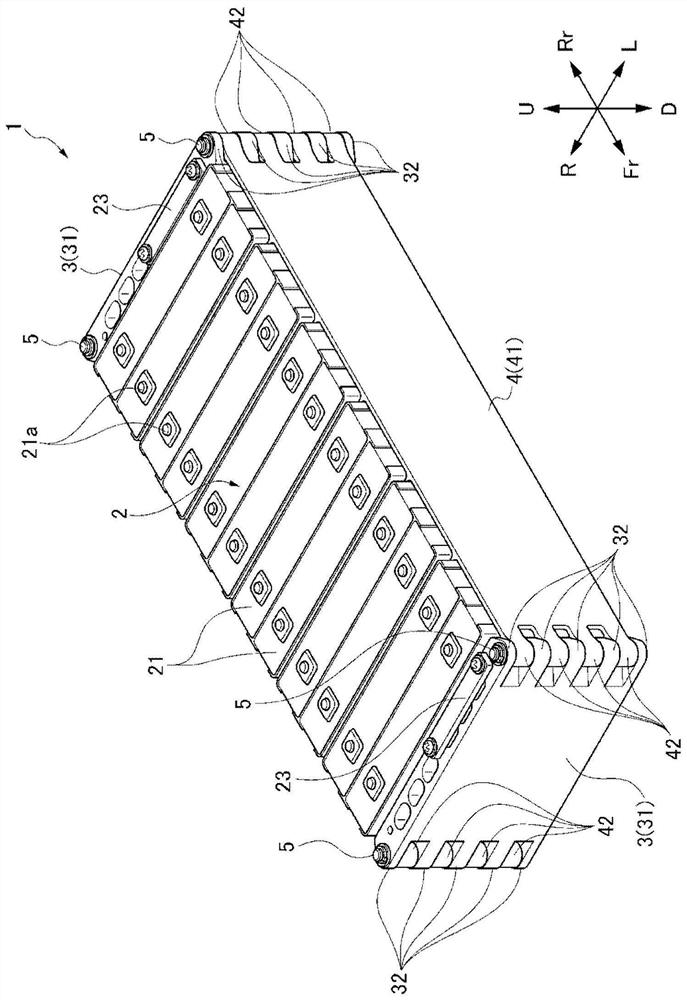
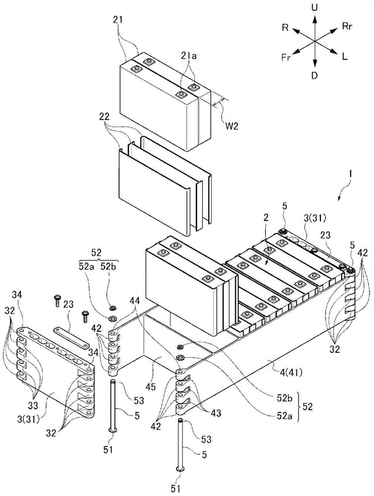
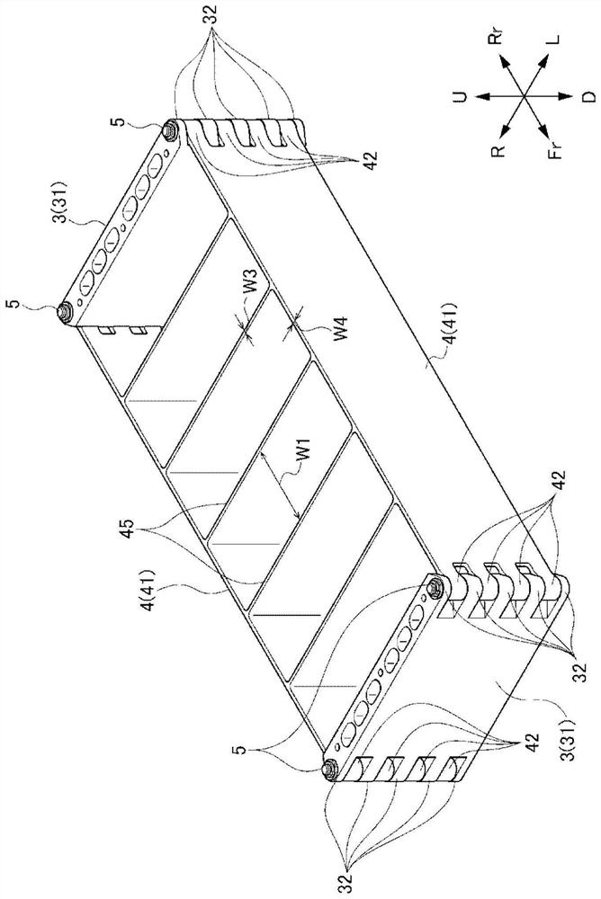
[0080] Such as Figure 1 to Figure 6 As shown, the battery module 1 according to the first embodiment of the present invention includes: a battery cell stack 2, which is formed by stacking a plurality of battery cells 21 in the front-rear direction, and has a front surface, a rear surface, a left surface, a right surface, an upper surface, and a lower surface; a pair of end plates 3 disposed on the front and rear surfaces of the cell stack 2; a pair of side frames 4 disposed on the left and right surfaces of the cell stack 2 and a plurality of connecting shafts 5, which connect the end plate 3 with the side frame 4.

[0081] It should be noted that, in this specification and the like, for the sake of simple and clear description, the stacking direction of the cells 21 is defined as the front-rear direction, and the direction perpendicular to the stacking direction of the cells 21 is defined as the left-right direction and the up-down direction. The front-back direction of the...

no. 2 approach

[0109] Next, refer to Figure 7 A battery module according to a second embodiment of the present invention will be described. Here, only the differences from the first embodiment will be described, and the description of the first embodiment will be referred to by using the same reference numerals as those in the first embodiment for the configurations common to the first embodiment.

[0110] Such as Figure 7 As shown, the difference between the battery module 1B according to the second embodiment and the first embodiment is that the bridging portion connecting the side frame main bodies 41B of the pair of side frames 4B is omitted, and the pair of side frames 4B are formed separately. of different parts.


PUM


Abstract

The present invention provides a battery module capable of suppressing the generation of bending stress at the connecting portion between an end plate and a side plate. The battery module (1) includes: a battery cell laminate (2), which is formed by stacking a plurality of battery cells (21) in the front-rear direction, and has a front surface, a rear surface, a left surface, a right surface, an upper surface, and a lower surface. surface; a pair of end plates (3), which are disposed on the front and rear surfaces of the single cell stack (2); and a pair of side frames (4), which are disposed on the right side of the single cell stack (2) And the left surface, wherein, the end portion of the end plate (3) and the end portion of the side frame (4) have an overlapping portion (R) when viewed from the up and down direction, and the overlapping portion (R) is provided with a A through-hole (34, 44) passes through, and a connecting shaft (5) passes through the through-hole (34, 44).

Description

technical field [0001] The present invention relates to a battery module mounted on an electric vehicle or the like. Background technique [0002] Conventionally, battery modules are mounted on electric vehicles and the like. For example, Patent Documents 1 and 2 disclose a battery module including a cell stack formed by stacking a plurality of cells in the front-rear direction and having a front surface, a rear surface, a left surface, a right a surface, an upper surface, and a lower surface; a pair of end plates disposed on the front and rear surfaces of the cell stack; and a fastening frame connecting the pair of end plates. [0003] In such a battery module, a load in the cell lamination direction of the battery module (hereinafter also appropriately referred to as a cell thickness constraint reaction force) occurs due to expansion of the cells due to temperature changes or aging. In recent years, as the capacity and energy density of single cells have increased, more ...

Claims


Application Information

Patent Timeline
Patent Type & Authority Patents(China)
IPC IPC(8): H01M50/242H01M50/204H01M50/244H01M50/249H01M50/209H01M50/224H01M50/296H01M50/55H01M50/553
CPCH01M2220/20H01M50/296H01M50/553H01M50/209H01M50/224H01M50/55B60L50/64B60L2270/145H01M10/0481H01M10/0486Y02T10/70Y02E60/10Y02P70/50
Inventor 樱井敦
Owner HONDA MOTOR CO LTD
Why Eureka
Try Eureka