Eureka AIR delivers breakthrough ideas for toughest innovation challenges, trusted by R&D personnel around the world.

A cable bridge for easy maintenance

A technology of cable trays and operating slots, applied in the direction of electrical components, etc., can solve the problems of limited number of cables, cumbersome and inconvenient cable operations, and achieve the effect of easy operation

Active Publication Date: 2019-01-15
JIANGSU JINLI ELECTRIC
View PDF9 Cites 0 Cited by
  • Summary
  • Abstract
  • Description
  • Claims
  • Application Information

AI Technical Summary

Problems solved by technology

[0005] The technical problem to be solved by the present invention is that when it is necessary to operate the cables in the bridge frame, since the cables are located at the bottom or corners of the bridge frame, the staff need to pull the cables out before operating, and pull them out under the action of manpower. The limited number of cables makes handling the cables cumbersome and inconvenient

Method used


Image

  • A cable bridge for easy maintenance
  • A cable bridge for easy maintenance
  • A cable bridge for easy maintenance

Examples


Embodiment Construction

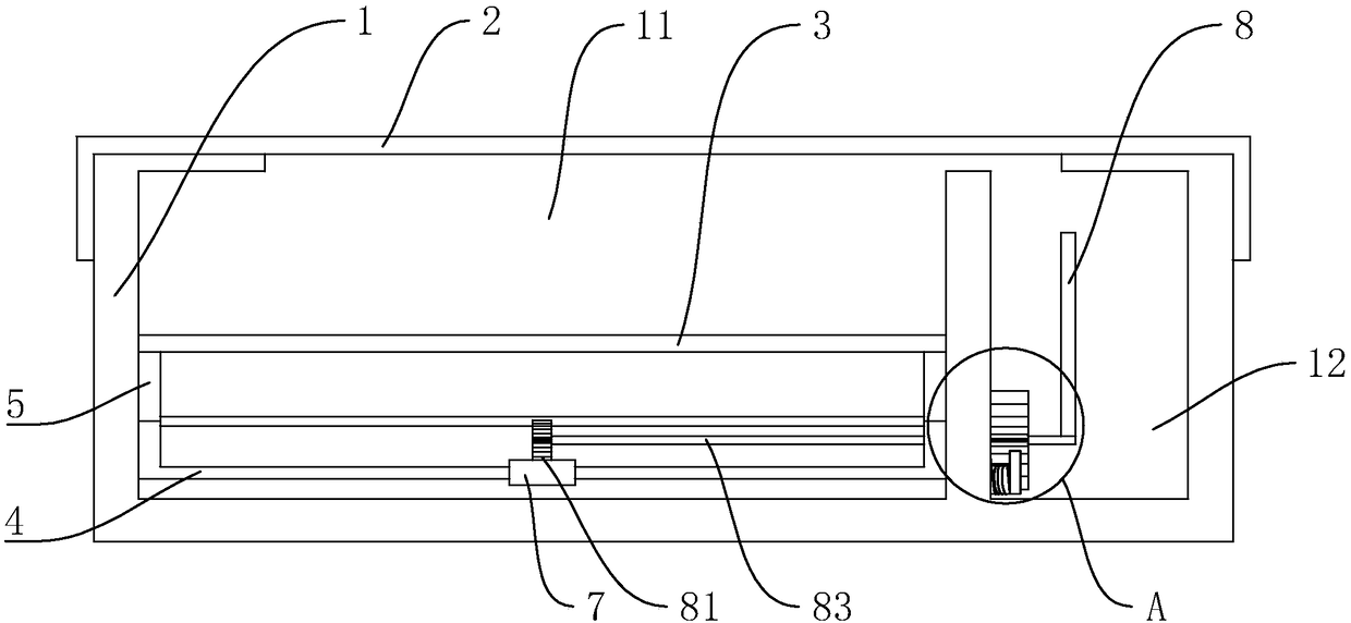
[0022] This embodiment provides an easy-to-maintain cable tray, the structure of which is as follows figure 1 , including a tank body 1 and a cover plate 2 covering the tank body 1 , the tank body 1 is divided into a wire slot 11 and an operation slot 12 along its width direction, and the width of the wire slot 11 is set to be greater than the width of the operation slot 12 .

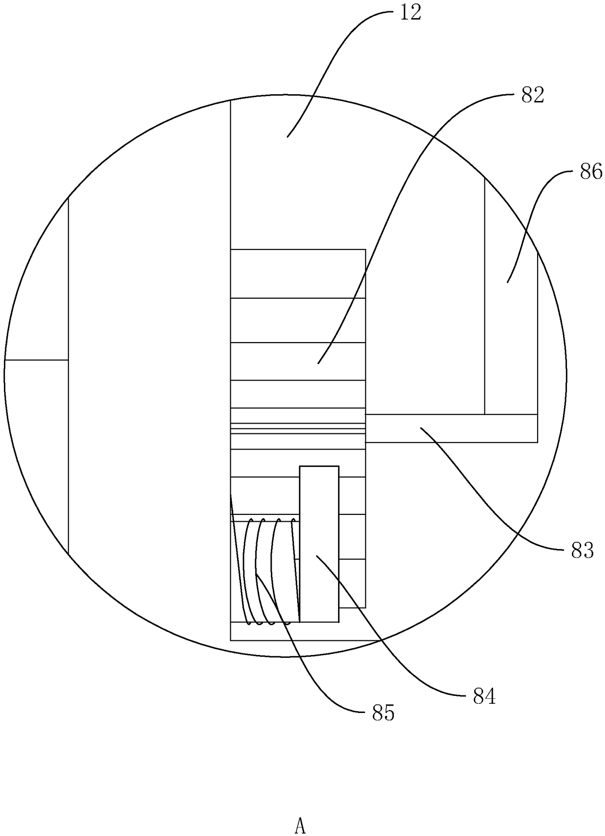
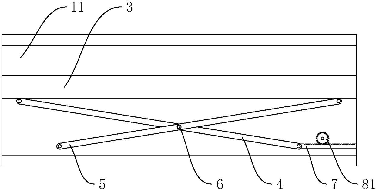
[0023] structured as Figure 2 to Figure 4 As shown, the bottom of the wiring trough 11 is provided with a supporting plate 3 for placing cables. The supporting plate 3 and the cover plate 2 are arranged horizontally, and the length of the supporting plate 3 is set to be equal to the length of the wiring trough 11. The length of the supporting plate 3 The lower side is provided with a first bracket 4 and a second bracket 5 that intersect each other. The first bracket 4 and the second bracket 5 are respectively hinged below the sides of the two ends of the length direction of the supporting plate 3. The ...


PUM


Abstract

The invention discloses a cable bridge which is convenient to maintain, A technical field of power line erection equipment is disclosed, by rotating the ratchet wheel to drive the driven gear to rotate in the same direction, and then driving the rack to move into the groove through the rotation of the driven gear, the rack also drives the lower end of the first bracket to slide into the groove, Asa result of that cross arrangement between the first bracket and the second bracket, and a rotating shaft is arranged at the intersection position of the two, so that when the lower end of the firststent is moved into the slot, that is, when the lower end of the first bracket and the lower end of the second bracket are in close proximity to each other, The upper end of the first bracket and theupper end of the second bracket are also close to each other, so that the upper ends of the first bracket and the second bracket move upward and drive the whole bracket plate to move upward so as to lift the cable on the bracket plate out of the groove body, thereby facilitating the operation of the worker and increasing the efficiency of the worker. The upper end of the first bracket and the upper end of the second bracket are also close to each other.

Description

technical field [0001] The invention relates to the technical field of power line erection equipment, in particular to a cable bridge frame which is convenient for maintenance. Background technique [0002] Cable trays are divided into trough type, tray type, ladder type, grid type and other structures, and are composed of brackets, supporting arms and installation accessories. It can be erected independently, and can also be laid on various buildings (structures) and pipe gallery supports. It reflects the characteristics of simple structure, beautiful appearance, flexible configuration and convenient maintenance. All parts need to be galvanized and installed in the building. If the exposed bridge is near the sea or in a corrosion area, the material must have the physical characteristics of anti-corrosion, moisture resistance, good adhesion, and high impact resistance. [0003] At present, the Chinese patent with the publication number CN203051958U discloses a cable tray, w...

Claims


Application Information

Patent Timeline
Patent Type & Authority Applications(China)
IPC IPC(8): H02G3/04
CPCH02G3/0406H02G3/0462
Inventor 朱朝平
Owner JIANGSU JINLI ELECTRIC
Why Eureka
Eureka Blog
Learn More