Rotor of an inner rotor motor

An inner rotor motor and rotor technology, which is applied to the rotor field of inner rotor motors, can solve the problems of loss of adhesion effect, deterioration and aging of adhesives, etc.

Active Publication Date: 2020-05-26
SUNONWEALTH ELECTRIC MACHINE IND
View PDF5 Cites 0 Cited by
  • Summary
  • Abstract
  • Description
  • Claims
  • Application Information

AI Technical Summary

Problems solved by technology

However, the adhesive itself has a certain lifespan, and the rotor structure is in a high-temperature, high-speed rotating environment for a long time, so the adhesive is easy to deteriorate and lose its adhesive effect

Method used


Image

  • Rotor of an inner rotor motor
  • Rotor of an inner rotor motor
  • Rotor of an inner rotor motor

Examples


no. 1 example

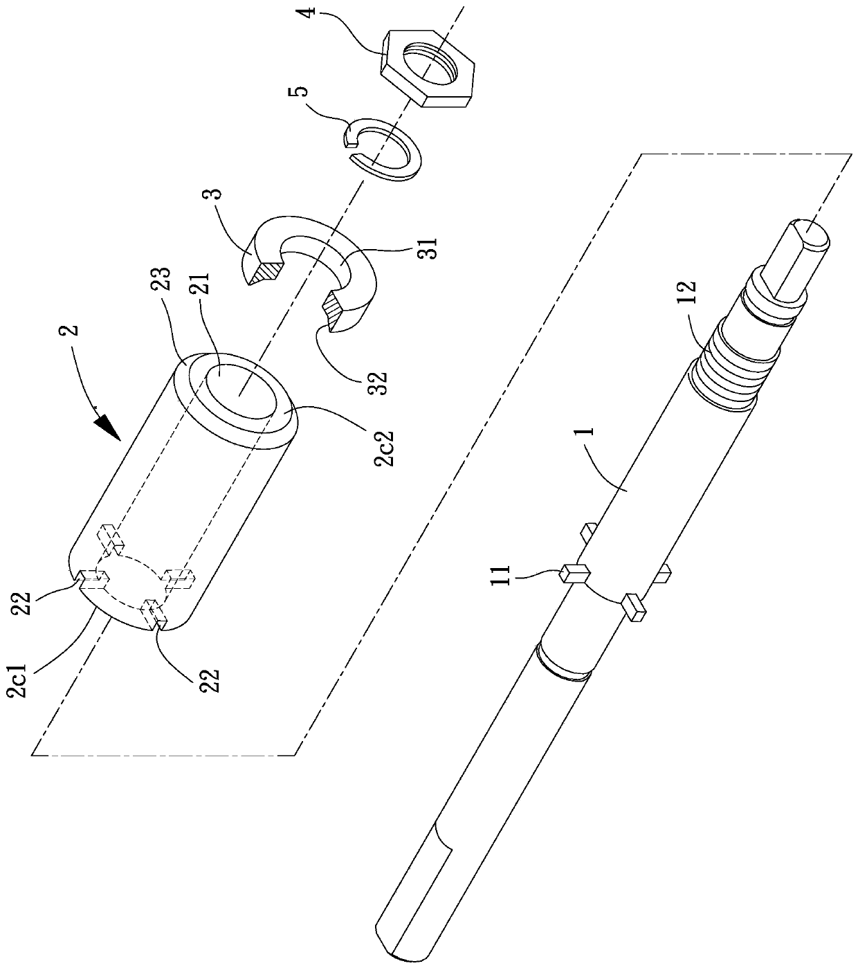
[0056] Please refer to figure 1 , which is the first embodiment of the rotor of the inner rotor motor of the present invention, the rotor of the inner rotor motor includes a rotating shaft 1, a permanent magnet 2 and a set of connectors 3, the permanent magnet 2 is arranged on the outer periphery of the rotating shaft 1 On the other hand, the assembly part 3 is sheathed on the rotating shaft 1 and combined with one end of the permanent magnet 2 .

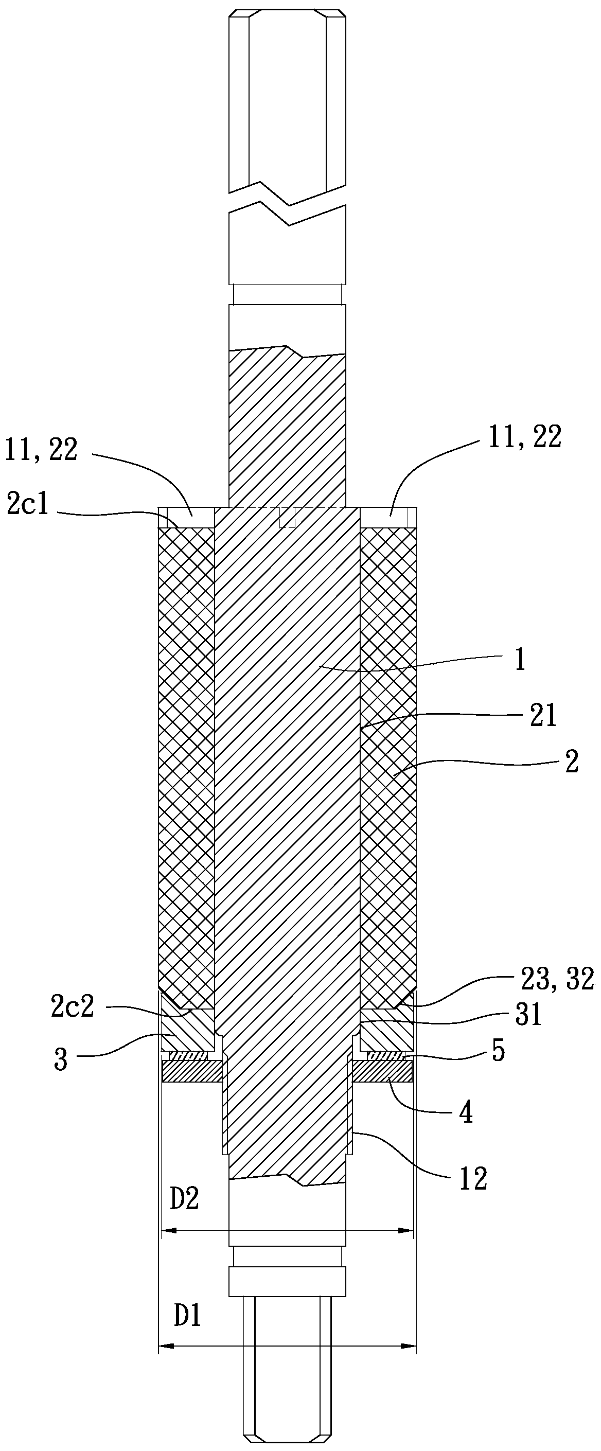
[0057] Please refer to figure 1 , 2, the rotating shaft 1 has at least one first positioning portion 11 and one second positioning portion 12, the at least one first positioning portion 11 is on the outer peripheral surface of the rotating shaft 1, the rotating shaft 1 is combined with the permanent magnet 2 The position has a section in the radial direction, and the section is preferably circular. The at least one first positioning portion 11 can be designed to protrude from the outer peripheral surface of the rotating shaft 1. I...


PUM


Abstract

A rotor for an inner rotor motor is provided for solving the problem of easy loosening between a rotating shaft of a conventional motor and a permanent magnet. The rotor of the inner-rotor motor of the present invention comprises: a rotating shaft having at least one first positioning portion; a permanent magnet disposed on the rotating shaft, the first end of the permanent magnet having at leastone first joint portion, the at least one first joint portion is combined with the at least one first positioning portion, and the second end of the permanent magnet has a second joint portion; and ajoint member sleeved on the rotating shaft via a through hole, wherein the joint member has a third joint portion, and the third joint portion is combined with the second joint portion of the permanent magnet.

Description

technical field [0001] The present invention relates to a rotor, especially a rotor of an inner rotor motor, the rotating shaft of which is combined with permanent magnets. Background technique [0002] The existing motor rotor structure has a rotating shaft and a permanent magnet. The permanent magnet is in the shape of a cylinder and has a shaft hole in the center. The permanent magnet can be sleeved on the rotating shaft so that the permanent magnet is combined with the rotating shaft. and rotate synchronously. [0003] Wherein, the combination method between the rotating shaft and the permanent magnet is to apply an adhesive between the rotating shaft and the shaft hole of the permanent magnet, so that the permanent magnet can be adhered to the rotating shaft and rotate synchronously . However, the adhesive itself has a certain lifespan, and the rotor structure is in a high-temperature, high-speed rotating environment for a long time, so the adhesive is easy to deterio...

Claims


Application Information

Patent Timeline
Patent Type & Authority Patents(China)
IPC IPC(8): H02K1/27
CPCH02K1/2706
Inventor 洪银树俞木凯梁胜杰
Owner SUNONWEALTH ELECTRIC MACHINE IND
Why Eureka
Try Eureka