Seal for pump
A technology for piston seals and sealing parts, which is applied to pump components, engine seals, variable-capacity pump parts, etc., can solve problems such as difficulty in ensuring sealing performance, and achieve improved confidentiality, fewer parts, and improved sealing. Effect
- Summary
- Abstract
- Description
- Claims
- Application Information
AI Technical Summary
Problems solved by technology
Method used
Image
Examples
no. 1 Embodiment
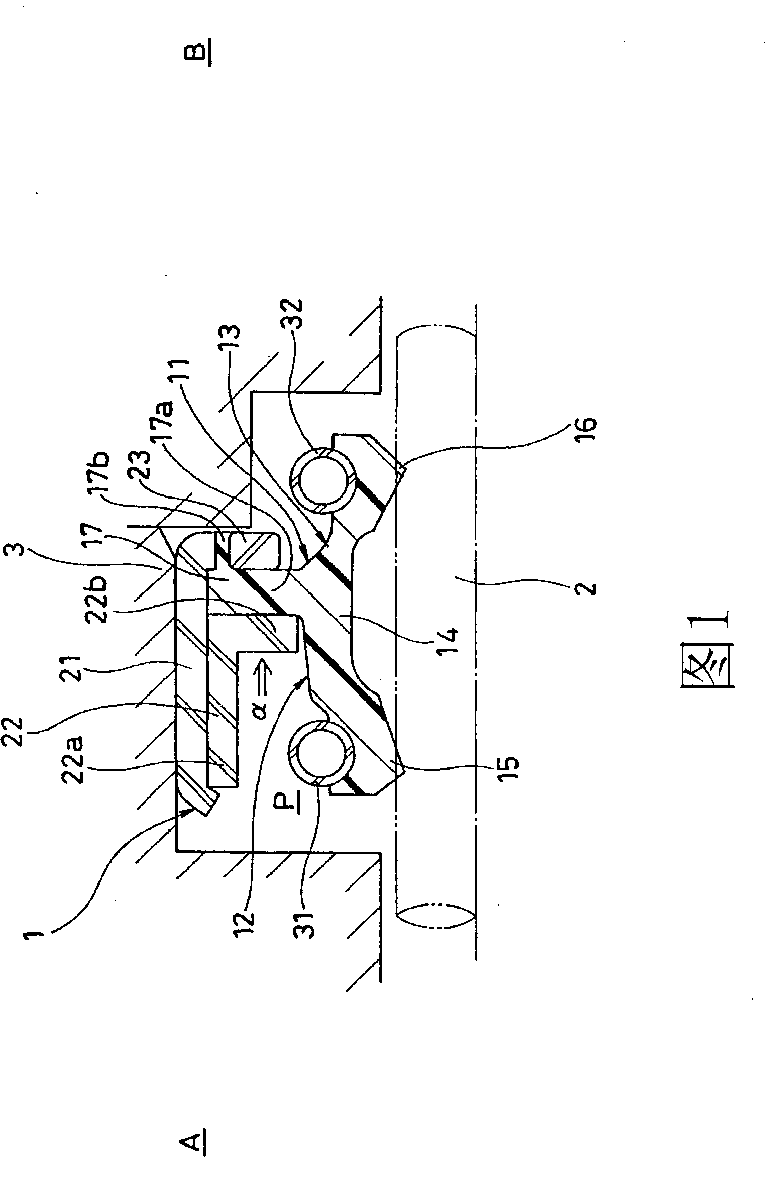
[0062] figure 1 It is a sectional view of a state in which the pump piston seal 1 according to the first embodiment of the present invention is installed in an annular space formed by a piston 2 and a housing 3 which are shafts reciprocating in a high-pressure fuel injection pump.
[0063] The pump piston seal 1 is used in fuel injection pumps for gasoline direct injection engines. It has the function of sealing gasoline and other fuels under high pressure on the side of the sealing object, and it is used for cooling or lubricating on the side of the anti-sealing object. Oil seal function.
[0064] exist figure 1 Among them, the pump piston seal 1 consists of a sealing member 11; three metal rings 21, 22, 23 holding the sealing member 11; Two coil springs 31, 32 of the lips 15, 16 are formed.
[0065] The three metal rings 21, 22, 23 consist of a first metal ring 21 fitted on the inner peripheral side of the housing 3, a cylindrical portion 22a fitted on the inner periphe...
no. 2 Embodiment
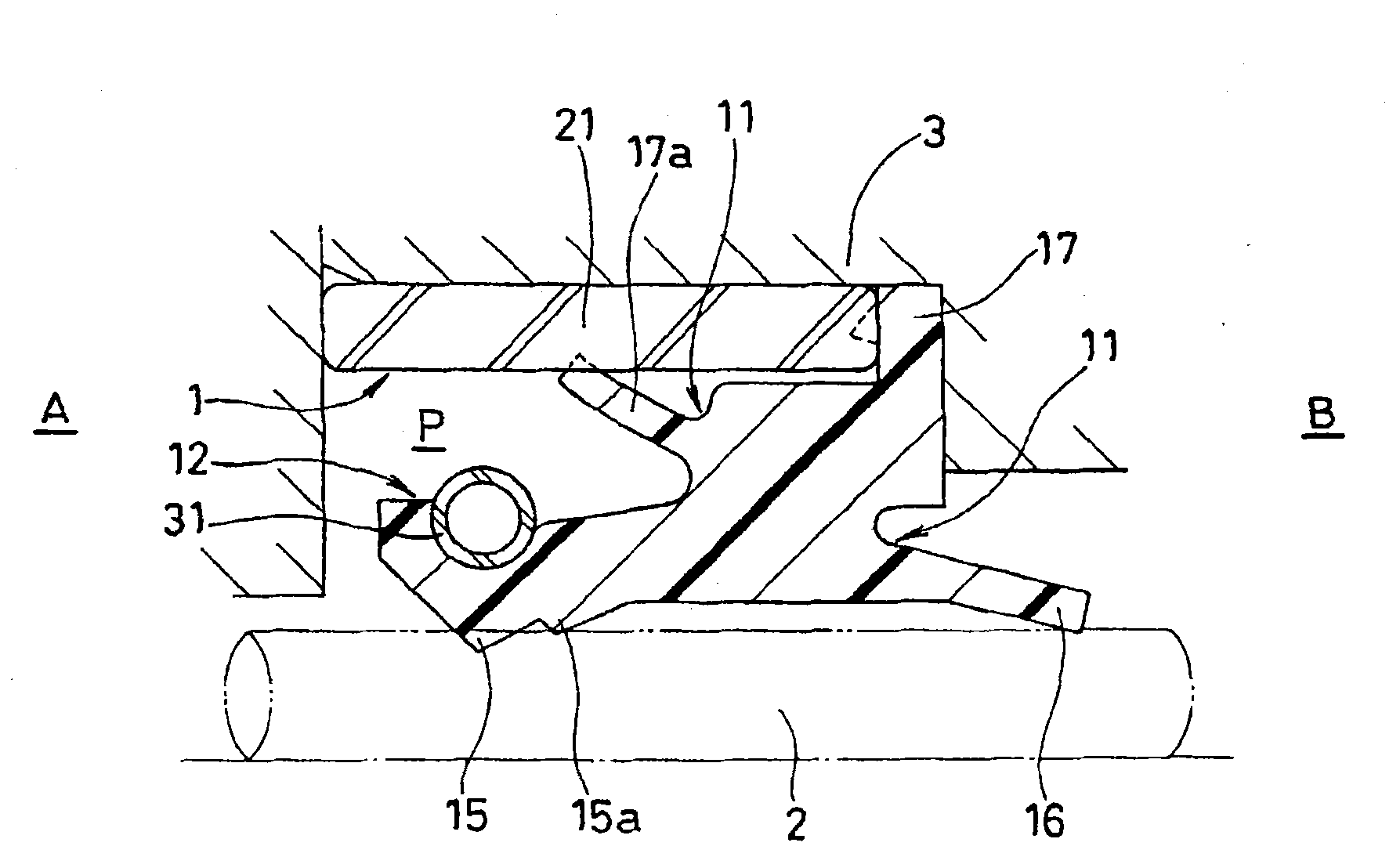
[0070] figure 2 It is a cross-sectional view of key parts of the pump piston seal 1 according to the second embodiment of the present invention.
[0071] exist figure 2 In the pump piston seal 1, different from the first embodiment, the sealing and fixing part 17 is clamped by the end surface of the casing 3 after the diameter is enlarged and the first metal ring 21, and has the function of sealing the inner peripheral side of the metal ring 21. The sealing lip 17a. No other ferrules are used. The fuel-side sealing lip 15 has an auxiliary lip 15a. In addition, since the seal lip 16 on the oil side has a rectangular cross-section and is reduced in diameter on the anti-seal side B, sealing performance is ensured, and therefore a coil spring is not used.
[0072] In the above structure, since the material of the sealing member 11 having the sealing lip 15 for sealing fuel and the sealing lip 16 for sealing oil is a resin material, and constitutes one sealing system integral...
no. 3 Embodiment
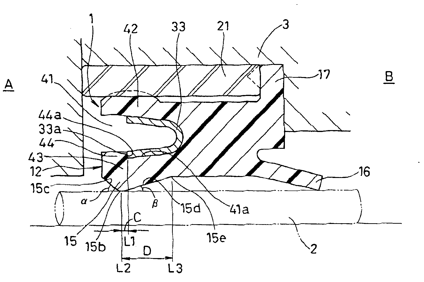
[0074] image 3 It is a cross-sectional view of key parts of the pump piston seal 1 according to the third embodiment of the present invention.
[0075] exist image 3 In the pump piston seal 1 of the present invention, the shape of the fuel seal member 12 is different from that of the second embodiment. That is, the fuel seal member 12 has a groove 41 opened on the side A to be sealed and has a substantially U-shaped cross section. The inner peripheral fixed sealing part 43 is formed, the metal ring 21 is fitted on the inner peripheral surface of the housing 3 , and the metal spring 33 imparting radial force is installed in the groove 41 . And no auxiliary lip 15a is provided.
[0076] The cross-sectional shape of the metal spring 33 is substantially U-shaped, and the front end surface 33a on the inner peripheral side is joined to the opening of the groove 41, that is, to the anti-sealing end surface 44a of the fixing shoulder 44 formed on the inner surface 41a on the pist...
PUM
 Abstract
Description
Claims
Application Information
 - R&D
- Intellectual Property
- Life Sciences
- Materials
- Tech Scout
- Unparalleled Data Quality
- Higher Quality Content
- 60% Fewer Hallucinations
Browse by: Latest US Patents, China's latest patents, Technical Efficacy Thesaurus, Application Domain, Technology Topic, Popular Technical Reports.
© 2025 PatSnap. All rights reserved.Legal|Privacy policy|Modern Slavery Act Transparency Statement|Sitemap|About US| Contact US: help@patsnap.com


