Multi-phase permanent magnet synchronous drive motor, application and method thereof

A drive motor and permanent magnet synchronization technology, which is applied to synchronous motors with stationary armatures and rotating magnets, magnetic circuit rotating parts, magnetic circuits, etc., can solve the problem of low utilization rate of motor iron core materials and thermal load of motors High, difficult heat dissipation of the motor, etc., to achieve the effect of low iron consumption, increase the total electric heating load, and high effective magnetic density of the air gap

Active Publication Date: 2020-04-10
山东艾克索仑电气有限公司
View PDF6 Cites 0 Cited by
  • Summary
  • Abstract
  • Description
  • Claims
  • Application Information

AI Technical Summary

Problems solved by technology

According to the knowledge of the inventor, most current multi-phase motors have the problems of magnetic flux leakage at the end and low utilization rate of the motor iron core material. The outer part of the rotor is the outer stator. The heat generated by the motor is concentrated in the axial direction of the motor. The thermal load of the motor is very high, and the inner stator is not connected to the external environment. It is difficult for the motor to dissipate heat.

Method used


Image

  • Multi-phase permanent magnet synchronous drive motor, application and method thereof
  • Multi-phase permanent magnet synchronous drive motor, application and method thereof
  • Multi-phase permanent magnet synchronous drive motor, application and method thereof

Examples


Embodiment 1

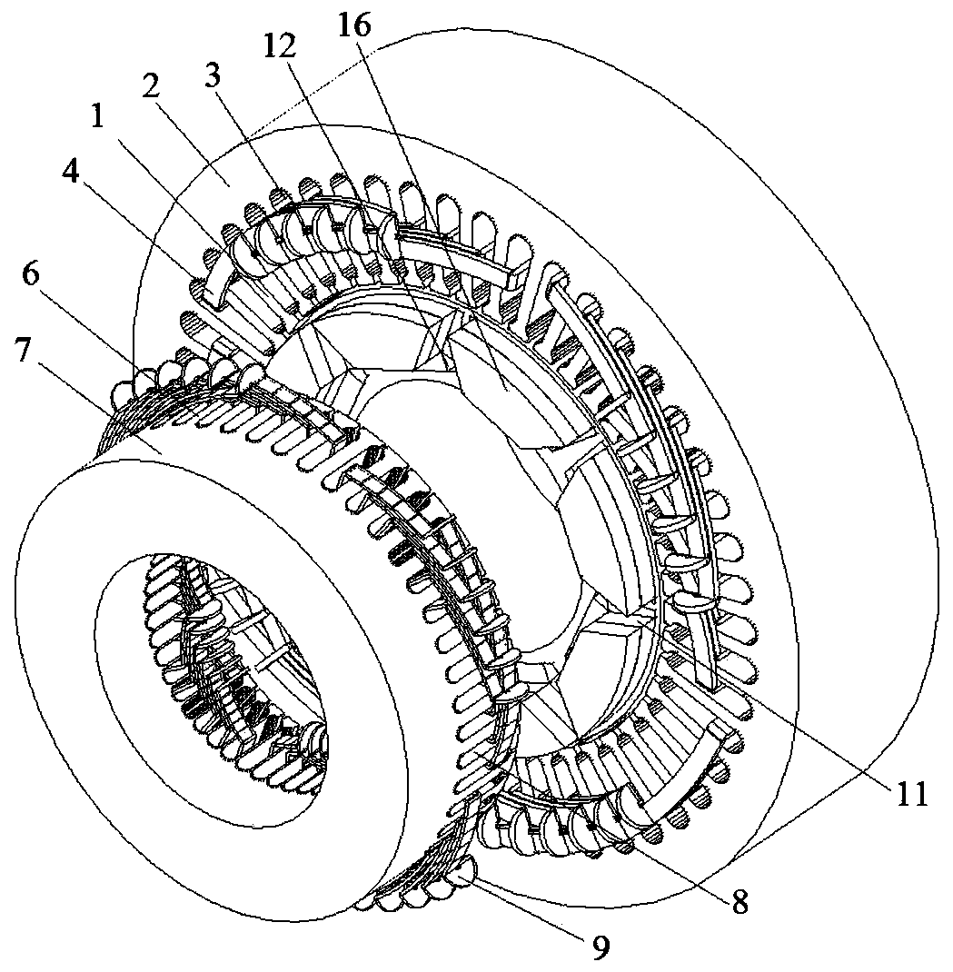
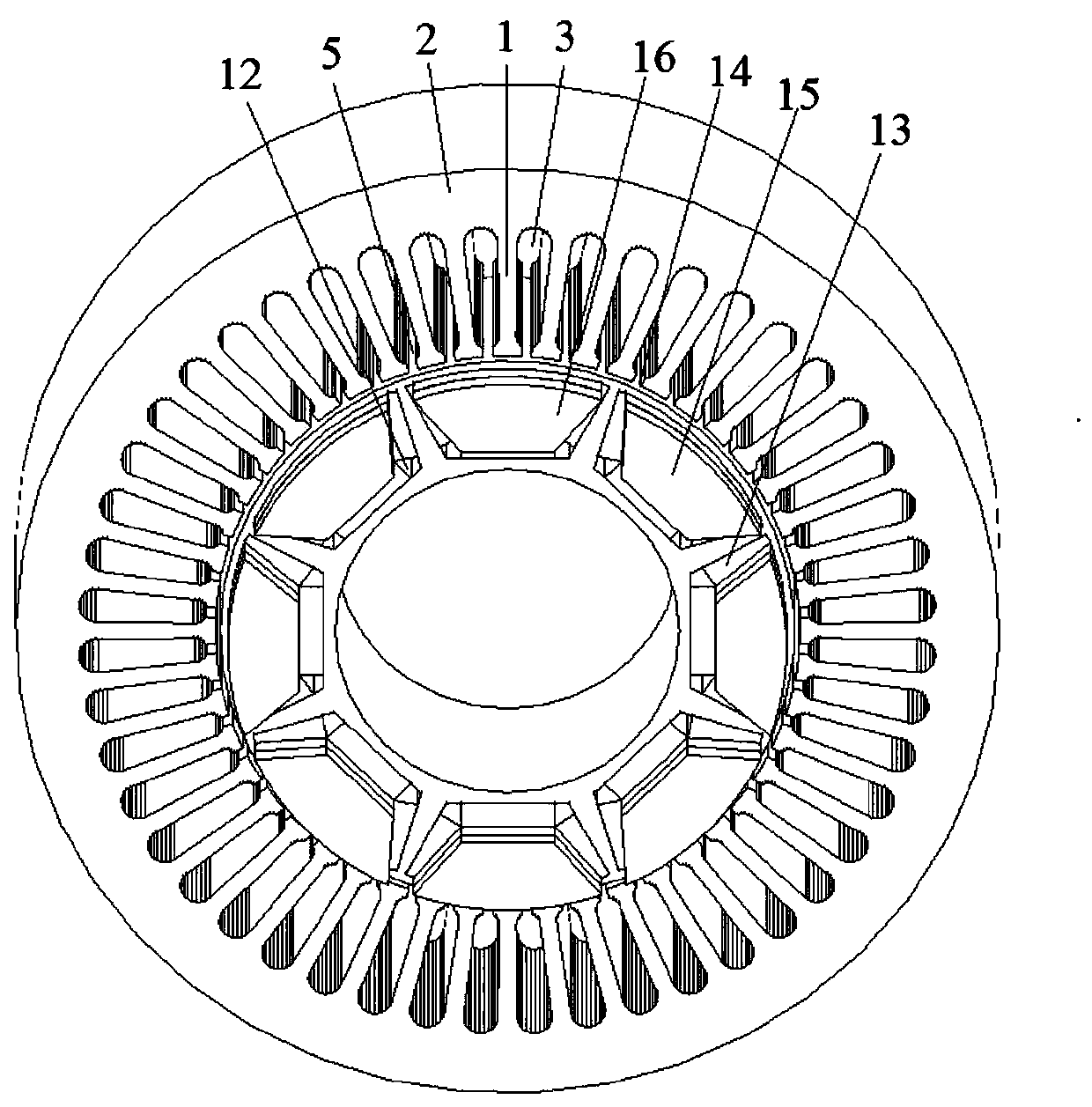
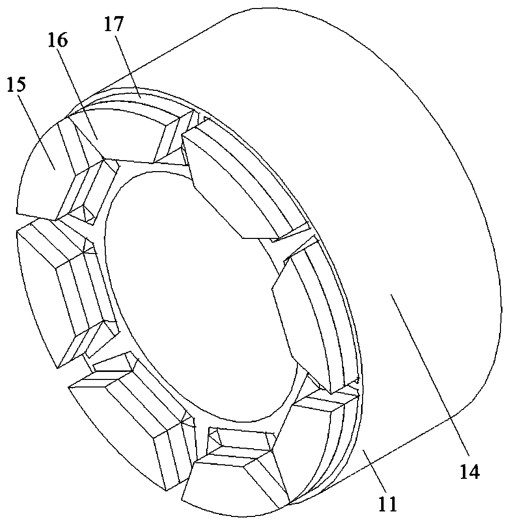
[0081] As shown in Figure 1(a)-Figure 1(e), the number of motor phases in this embodiment is 6, the number of radial stator teeth is 48, the number of axial stator teeth is 48, the number of rotor slots is 8, and the number of radial magnetic poles is 8 , the number of axial magnetic poles is 8, one end of the rotor has a fan ring structure, and a permanent magnet is attached to the fan ring, and the polarity generated by the permanent magnet on the fan ring on the iron core side is the same as that generated by the permanent magnet in the rotor slot The polarity of the axial magnetic flux is the same. This embodiment includes a radial stator, an axial stator and a rotor. The radial stator is made of laminated silicon steel sheets. The radial stator includes radial stator teeth 1, radial stator yoke 2 and radial To the stator slot 3, radial armature windings 4 are placed in the radial stator slots 3. The radial armature windings 4 can be divided into distributed windings, conce...

Embodiment 2

[0083] As shown in Figure 2(a)-Figure 2(e), the main difference between Embodiment 2 and Embodiment 1 is that (1) there are axial stators at both ends of the motor in Embodiment 2, and the motor has soft magnetic The two ends of the composite rotor core are processed into the shape of the fan ring to form the axial magnetic poles, but in the first embodiment, only one end of the motor has an axial stator, and only one end of the motor rotor core is processed into a fan ring. The shape forms the axial magnetic pole. (2) In the second embodiment, because the two sections of the rotor are all processed into the shape of the fan ring, the number of permanent magnets that need to be surface-mounted on the fan ring increases. The structure in the second embodiment, because the two ends of the rotor Both have rotors that eliminate unbalanced magnetic pull on the rotors. In this embodiment, the number of motor phases is 6, the number of radial stator teeth is 48, the number of axial s...


PUM


Abstract

At least one end of that rotor is provide with an axial stator, and the axial stator is concentrically arranged with the rotor; The stator slot of the radial stator is provided with a radial winding,The axial stator is divided into a radial stator and an axial stator, and the axial stator is arranged at the end of the rotor, so that the magnetic leakage effect at the end of the motor can be reduced, the heat dissipation efficiency can be improved, and the power density of the motor is increased by sticking a permanent magnet on the end of the rotor, so that the multi-phase control is easy torealize.

Description

technical field [0001] The present disclosure relates to a multi-phase permanent magnet synchronous drive motor, an application and a method thereof. Background technique [0002] The statements in this section merely provide background information related to the present disclosure and do not necessarily constitute prior art. [0003] With the improvement of high temperature resistance and price reduction of permanent magnet materials, permanent magnet motors have been widely used in national defense, industry, agriculture and daily life, and are developing in the direction of high power, high functionality and miniaturization. The variety and application fields of magneto are constantly expanding. At present, the power of permanent magnet motors ranges from a few milliwatts to thousands of kilowatts, and the application scope ranges from small toy motors to large permanent magnet motors used in ship traction. They are used in various aspects of the national economy, daily ...

Claims


Application Information

Patent Timeline
Patent Type & Authority Patents(China)
IPC IPC(8): H02K21/14H02K1/27
CPCH02K1/276H02K1/278H02K21/14
Inventor 王道涵彭晨
Owner 山东艾克索仑电气有限公司
Why Eureka
Try Eureka