Key jitter-removing method, device and storage medium

A storage medium and button technology, applied in the field of communication, can solve problems such as button signal glitches, and achieve the effect of solving glitches

Inactive Publication Date: 2019-01-15
ZTE CORP
View PDF4 Cites 6 Cited by
  • Summary
  • Abstract
  • Description
  • Claims
  • Application Information

AI Technical Summary

Problems solved by technology

[0008] The main purpose of the present invention is to propose a button debounce metho

Method used


Image

  • Key jitter-removing method, device and storage medium
  • Key jitter-removing method, device and storage medium
  • Key jitter-removing method, device and storage medium

Examples


no. 1 example

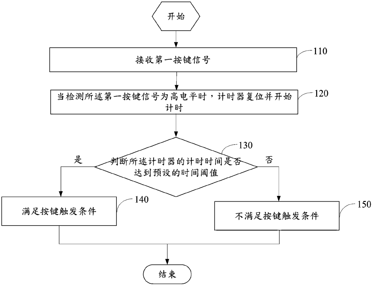
[0029] like figure 1 As shown, a preferred embodiment of the present invention provides a button debounce method, the shown method includes steps:

[0030] Step 110, receiving a first key signal.

[0031] Specifically, when the user presses the mechanical key and the pressing operation is an effective operation, the circuit where the mechanical key is located is triggered to generate a first key signal and receive the first key signal.

[0032] Further, according to the voltage condition of the circuit, the first button signal may be at a high level or at a low level.

[0033] Further, according to the first key signal, the device may respond to an operation corresponding to the first key signal.

[0034] Step 120, when it is detected that the first key signal is at a high level, the timer is reset and starts counting.

[0035] Specifically, when it is detected that the first button signal is at a high level, the timer is reset to 0 and starts counting.

[0036] Step 130, ...

no. 2 example

[0053] like Figure 4 As shown, another preferred embodiment of the present application provides a button debounce device, which includes:

[0054] The receiving module 410 is configured to receive the first key signal.

[0055] Specifically, when the user presses the mechanical key, and the pressing operation is an effective operation, the circuit where the mechanical key is located is triggered to generate a first key signal, and the receiving module 410 receives the first key signal.

[0056] Further, according to the voltage condition of the circuit, the first button signal may be at a high level or at a low level.

[0057] Further, according to the first key signal, the device may respond to an operation corresponding to the first key signal.

[0058]The timing module 420 starts timing when it detects that the first button signal is at a high level.

[0059] Specifically, when it is detected that the first button signal is at a high level, the timing module 420 resets ...

no. 3 example

[0070] Another embodiment of the present application provides a device. Based on the foregoing embodiments, the device includes a button, a timer, a processor, and a memory. Wherein, the button is used to conduct with the button circuit and generate a button signal, the timer is used to detect the button signal and time the button signal, and the processor is used to execute the button debounce program stored in the memory to achieve the following steps:

[0071] receiving the first button signal;

[0072] When detecting that the first button signal is at a high level, the timer is reset and starts counting;

[0073] Judging whether the time counted by the timer reaches a preset time threshold; if yes, the key trigger condition is met; if not, the key trigger condition is not met.

[0074] Specifically, when the user presses the mechanical key and the pressing operation is an effective operation, the circuit where the mechanical key is located is triggered to generate a first...


PUM


Abstract

The invention discloses a key jitter-removing method, a device and a storage medium, and belongs to the technical field of communication. The method includes the steps of receiving a first key signal;when it is detected that the first key signal is in a high level, a timer is reset and starts timekeeping; determining whether the time of the timer reaches a preset time threshold; if not, a key trigger condition is not satisfied. According to the key jitter-removing method, the device and the storage medium of the present invention, if a key signal received during a period from the start of thetimekeeping to the maximum time is determined as a glitch signal, the state of the key trigger condition is not satisfied such that an operation of the glitch signal is not triggered, thereby solvingthe glitch of the key and achieving a key jitter-removing effect.

Description

technical field [0001] The present invention relates to the technical field of communication, in particular to a button debounce method, device and storage medium. Background technique [0002] Buttons are widely used in various control devices. Since the button signal is generated mechanically, the button signal always has glitches due to mechanical contact. [0003] At present, the processing method for the glitches that appear in the button signal is to delay for a period of time when receiving the button press signal, and then judge the button state again when the button state is stable. If the button is still in the pressed state, the button is pressed Corresponding processing. [0004] However, existing processing methods have the following deficiencies: [0005] 1. Because it needs to be judged after a delay, it cannot respond to the button immediately; [0006] Second, it is necessary to judge the state of the button twice, which increases the complexity. [0007...

Claims


Application Information

Patent Timeline
IPC IPC(8): H03K17/22
CPCH03K17/22H03K2217/9401
Inventor 何健
Owner ZTE CORP
Why Eureka
Try Eureka