Image display method, device and system

An image display and panoramic image technology, applied in the field of image processing, can solve the problems of image occupation in close-up areas, multiple network resources, etc.

Active Publication Date: 2019-01-15
HANGZHOU HIKVISION DIGITAL TECH
View PDF7 Cites 11 Cited by
  • Summary
  • Abstract
  • Description
  • Claims
  • Application Information

AI Technical Summary

Problems solved by technology

[0005] In order to solve the problem that the method in the related art occupies more network resources when displaying close-up area images, the present invention provides an image display method, device and system

Method used


Image

  • Image display method, device and system
  • Image display method, device and system
  • Image display method, device and system

Examples


Embodiment Construction

[0098] In order to make the object, technical solution and advantages of the present invention clearer, the implementation manner of the present invention will be further described in detail below in conjunction with the accompanying drawings.

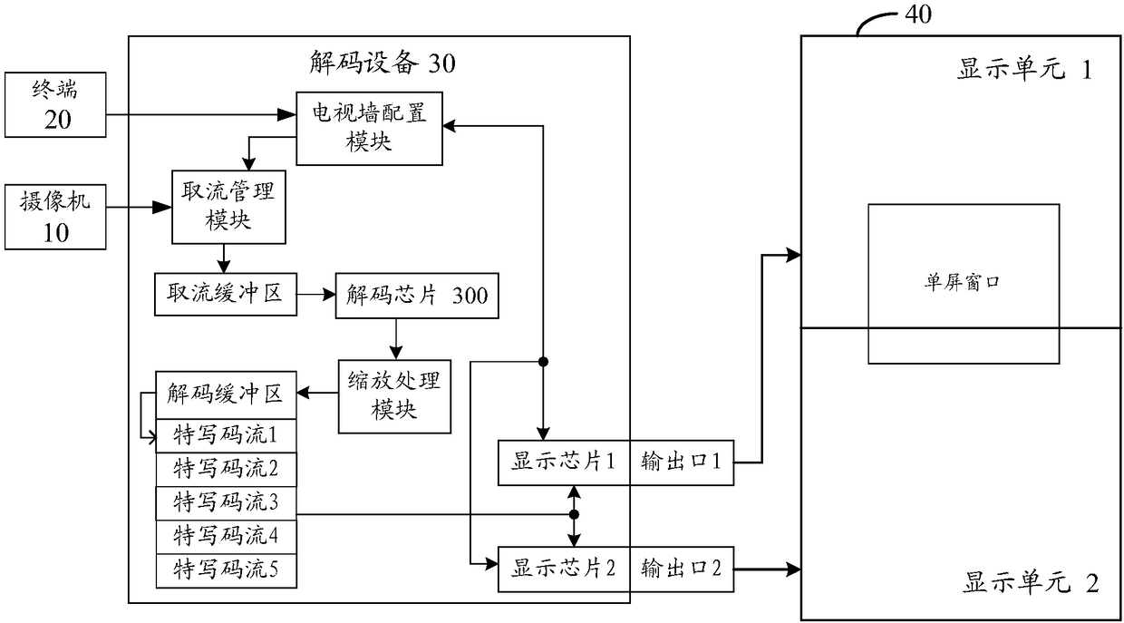
[0099] figure 2 is an architecture diagram of an image display system provided by an embodiment of the present invention, refer to figure 2 , the system may include a camera 10, a terminal 20, a decoding device 30 and a video wall 40, and the video wall 40 may include a plurality of display units ( figure 2 Display unit 1 and display unit 2 are shown in ). refer to figure 2 It can be seen that the decoding device 30 can be configured with a TV wall configuration module, a decoding chip 300 and a plurality of display chips, wherein each display chip corresponds to a display unit for storing the code stream to be displayed in the display unit. The TV wall configuration module can receive the control instruction issued by the termi...


PUM


Abstract

The invention discloses an image display method, device and system, and belongs to the technical field of image processing. The method includes receiving a close-up display instruction sent by a terminal; acquiring a close-up code stream corresponding to a close-up area from a video code stream of a panoramic image according to the location information of the close-up area in the panoramic image;and outputting the close-up code stream to a corresponding display unit. During the display of the close-up image, a decoding device can directly process the acquired video code stream of the panoramic image without acquiring the close-up code stream from a camera, thereby avoiding occupying excessive network resources.

Description

technical field [0001] The present invention relates to the technical field of image processing, and in particular, to an image display method, device and system. Background technique [0002] refer to figure 1 , the currently commonly used video surveillance system generally includes at least one camera 01, a terminal 02, a decoding device 03 and a video wall 04, and the video wall 04 is formed by splicing a plurality of display units. Each camera 01 is used to collect video code streams, and can transmit the collected video code streams to the decoding device 03 through the communication network; the decoding device 03 is used to decode each video code stream and output it to the corresponding video wall 04 The video wall 04 can display the monitoring images collected by multiple cameras at the same time. The terminal 02 is used for overall control of the decoding device 03, for example, the identification of the camera 01 can be issued to the decoding device 03, so that...

Claims


Application Information

Patent Timeline
Patent Type & Authority Applications(China)
IPC IPC(8): H04N7/18H04N5/262H04N5/265
CPCH04N5/2624H04N5/265H04N7/18
Inventor 吴尚杰宋义陈王贤周建
Owner HANGZHOU HIKVISION DIGITAL TECH
Why Eureka
Try Eureka