Tray achieving rapid watering

A pot-supporting and fast technology, which is applied to automatic watering devices, dish pads for flowerpots, container cultivation, etc., can solve the problems of insufficient soil moisture, poor water absorption capacity, and affecting plant growth.

Pending Publication Date: 2019-01-18
舒雷翔
View PDF0 Cites 0 Cited by
  • Summary
  • Abstract
  • Description
  • Claims
  • Application Information

AI Technical Summary

Problems solved by technology

At present, there are two watering methods for potted plants. One is to water directly on the soil surface of the potted plants. The watering process is more convenient and saves trouble. The gap between the pot and the flowerpot flows directly from the drainage hole, causing insufficient soil moisture and affecting plant growth
Another method is to water through the drainage hole at the bottom of the flowerpot, specifically: put the flowerpot into a support basin filled with water and immerse the drainage hole at the bottom into the water, and through the adsorption of water by the soil, Water can slowly infiltrate into the soil from bottom to top, increasing the overall water content of the soil, which is beneficial to the growth of plants, but it takes a long time to adopt this method, especially for people who plant a lot of potted plants at home. a lot of time and effort

Method used


Image

  • Tray achieving rapid watering
  • Tray achieving rapid watering
  • Tray achieving rapid watering

Examples


Embodiment Construction

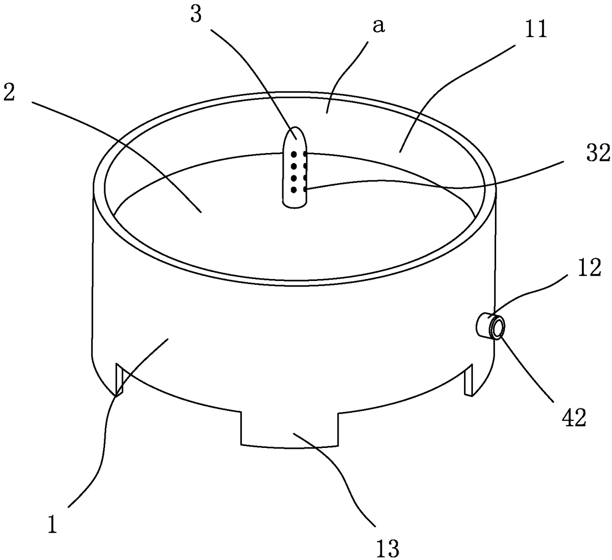
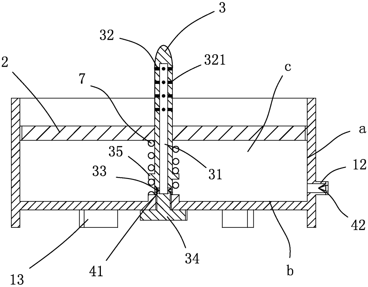
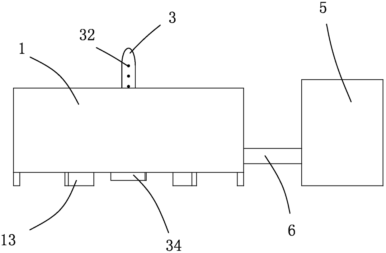
[0022] The specific embodiment of the support basin that can water quickly in the present invention is for example Figure 1-3 As shown, the basin body 1 is included, and the basin body 1 includes a concave cavity 11. The transverse section of the concave cavity 11 can be a regular polygon, but it is preferably circular. The sliding piston plate 2 is provided with an upwardly extending convex column 3 at the bottom inner wall b of the concave cavity 11, and the piston plate 2 is slidably sleeved on the convex column 3. The connection between them constitutes a sliding sealing fit, and the sliding sealing fit means that a seal between the two can be formed while being able to slide relatively. A sealing lip made of rubber material is set to realize sliding and sealing cooperation, and a water storage chamber c is formed between the piston plate 2 and the bottom inner wall b of the concave cavity 11, and the water storage cavity c is composed of the piston plate 2 and the inner ...


PUM


Abstract

The invention discloses a tray achieving rapid watering. The tray comprises a tray body which comprises a cavity, a piston plate capable of sliding vertically along the inner side wall of the cavity is arranged in the cavity, a convex column extending upwards is arranged on the bottom inner wall of the cavity, the piston plate slidably sleeves the convex column, sliding seal fit is formed at the joints of the piston plate and the convex column and concave inner side wall, a water storage cavity is formed between the piston plate and the bottom inner wall of the cavity, the convex column comprises a water passage extending in the length direction of the convex column, multiple water outlets communicated with the water passage are formed in the portion, close to the upper end, of convex column, and water inlets communicated with the water passage are formed in the portion, close to the lower end of the bottom inner wall of the cavity, of the convex column. The tray is simple in structure, the watering speed and effect can be improved, the watering process is more convenient, and plant growth is facilitated.

Description

technical field [0001] The invention relates to a support basin capable of rapid watering. Background technique [0002] Potted plants need to be watered frequently during the planting process. Traditionally used for potted planting, there is usually a drainage hole in the center of the bottom. The drainage hole can not only discharge excess water when watering too much, but also allow the outside air to Into the bottom of the soil, which is conducive to the respiration of plant roots. At present, there are two watering methods for potted plants. One is to water directly on the soil surface of the potted plants. The watering process is more convenient and saves trouble. The gap between the pot and the flowerpot flows directly from the drainage hole, causing insufficient soil moisture and affecting plant growth. Another method is to water through the drainage hole at the bottom of the flowerpot, specifically: put the flowerpot into a support basin filled with water and imme...

Claims


Application Information

Patent Timeline
IPC IPC(8): A01G9/04A01G27/02A01G9/02
CPCA01G9/04A01G9/02A01G9/047A01G27/02
Inventor 舒雷翔
Owner 舒雷翔
Why Eureka
Try Eureka