
Electric scraper device for sintering cylinder mixer

A cylinder mixing and scraper device technology, which is applied in the field of metallurgical equipment and scraping equipment, can solve the problems of increasing the operating load of the cylinder mixer, threatening the personal safety of workers, reducing the production output of the cylinder mixer, and improving the operation of the equipment. Reliability, simplification of transmission system structure, and high promotion and use value

Active Publication Date: 2019-01-18
YANSHAN UNIV
View PDF33 Cites 0 Cited by
  • Summary
  • Abstract
  • Description
  • Claims
  • Application Information

AI Technical Summary

Problems solved by technology

In order to reduce sticking, many companies now use nylon liners in their drum mixers, which improves material sticking, but has poor wear resistance, short service life, and still has sticking to varying degrees. It is difficult to clean the material on the inner wall of the cylinder, which will increase the operating load of the cylinder mixer, reduce the production output of the cylinder mixer, and especially have a negative impact on the pelletizing effect of the secondary mixer.
[0004] The traditional method of cleaning the materials of the cylindrical mixer is usually manual cleaning on a regular basis, which increases the labor intensity of the workers. At the same time, the internal lining board is easily damaged during the cleaning process, and it is easy to cause the inside of the mixer to collapse, causing the water spray pipe and hanging The damage of the wire rope even threatens the personal safety of workers
[0005] In order to solve the problem of cylinder sticking of the mixer, two structural types of cleaning devices or scrapers are usually used. One is the structural type of fixed scrapers arranged closely along the direction of the generatrix of the cylinder wall of the cylindrical mixer. In this structural type, along the The length direction of the cylinder mixer is in contact with the material, the scraping resistance is huge, and the power consumption of the mixer is relatively large. The name is a device for removing sticky material in the mixer
At the same time, the improvement method of this structure is a structural type in which scrapers are arranged at intervals, and a certain distance is left in the middle of each group of scrapers, such as patent number ZL201120280569. .6. The name of the invention is an online cleaning device for viscous materials in mixers. Although the contact length is reduced and the scraping resistance is reduced, it cannot scrape materials along the entire length of the cylindrical busbar, so there are still some materials Sticking phenomenon; Another type is to let one or more scrapers move along the direction of the busbar of the mixer, such as the patent number ZL201120415173.1, the invention name is the scraper device of the mixer, and the scraper can move along the circle under the drive of the new power. The reciprocating movement in the direction of the busbar of the cylinder increases the scraping range with fewer scrapers, but it is difficult to perform all-round scraping in the production state of the cylinder mixer, and the mixer needs to be stopped regularly for scraping, and the structure is complex, increasing new power consumption and control system

Method used


Image

  • Electric scraper device for sintering cylinder mixer
  • Electric scraper device for sintering cylinder mixer
  • Electric scraper device for sintering cylinder mixer

Examples


Embodiment Construction

[0032] The following examples are only used to explain the present invention, so as to understand the implementation process of the present invention, and do not constitute a limitation to the protection scope of the present invention.

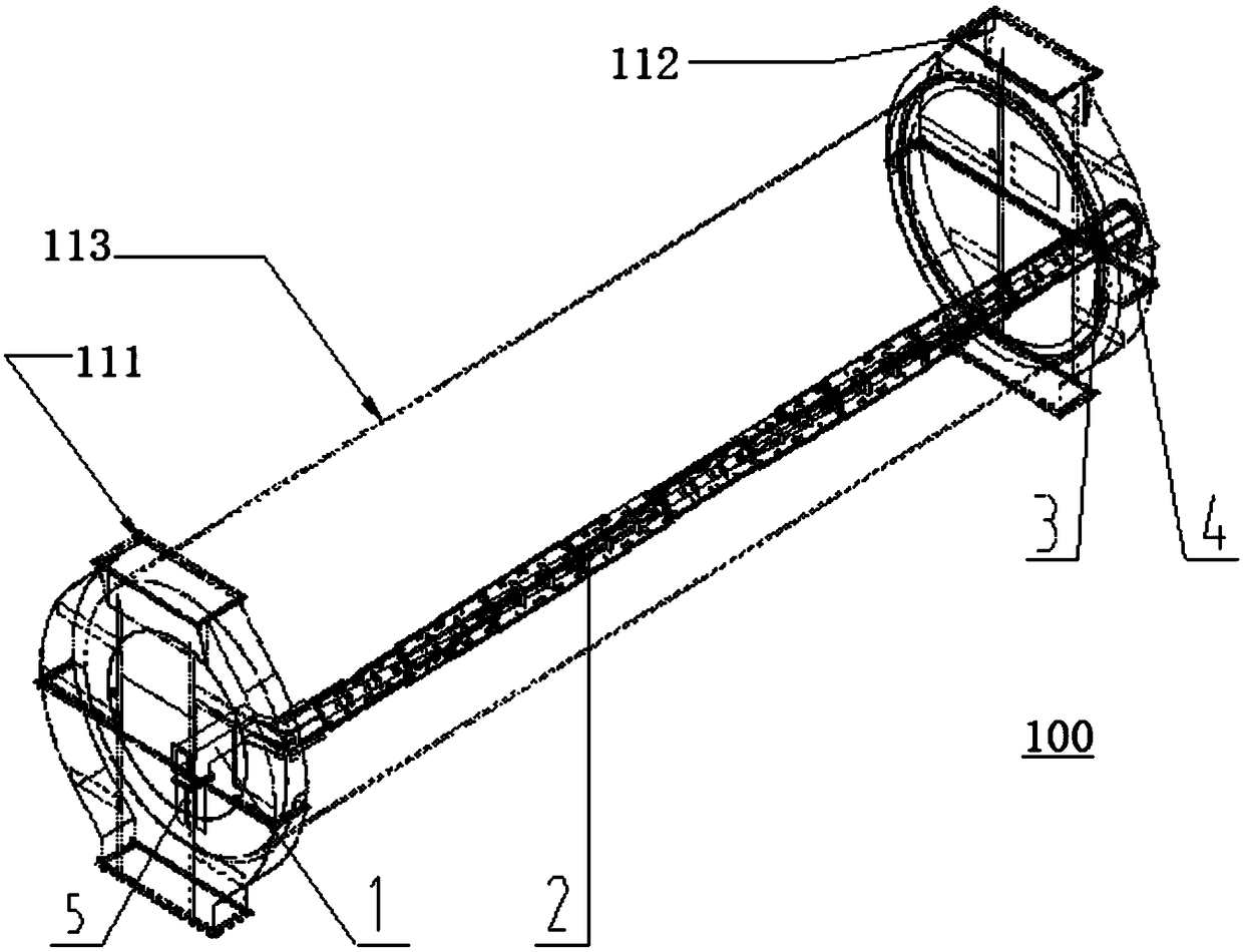
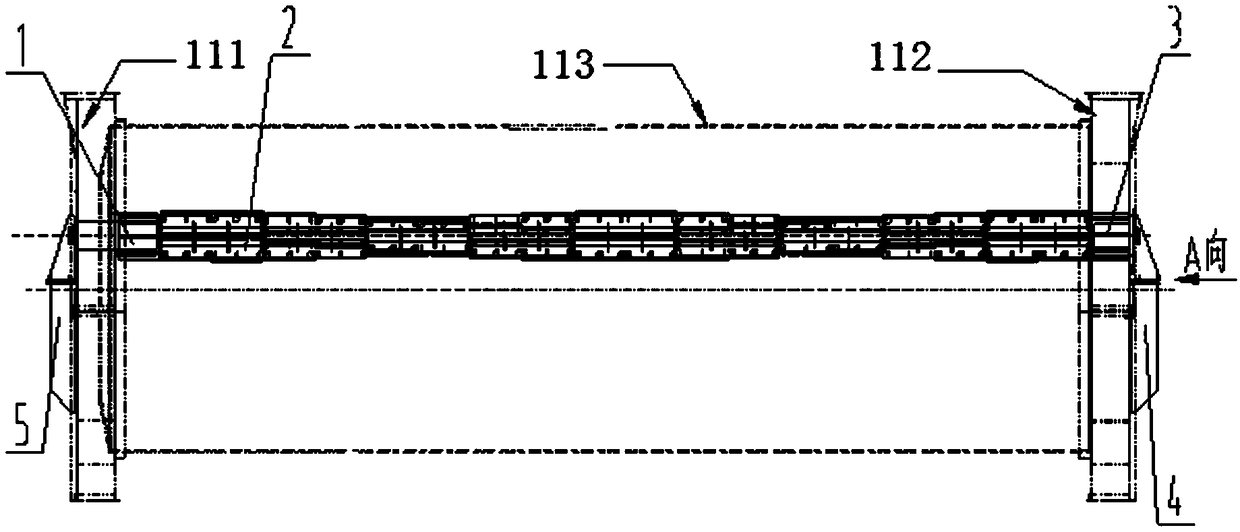
[0033] as attached figure 1 , attached figure 2 As shown, the electric scraper device 100 for the sintering cylinder mixer of the present invention includes a front transmission assembly 1, a cage scraper assembly 2 and a rear transmission assembly 3, wherein the electric cage scraper assembly 2 passes through the front transmission assembly 1 and the rear transmission assembly 3 The connecting flange is fixedly installed with the front support 5 and the rear support 4 of the drum mixer.

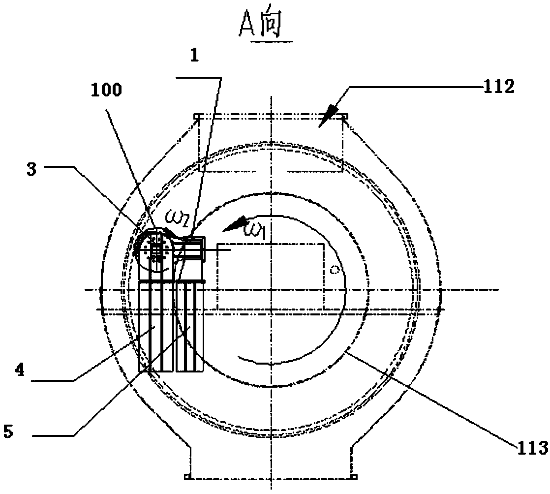
[0034] as attached image 3 As shown, the electric scraper device 100 for the sintering cylinder mixer of the present invention is installed on the opposite side of the material lifting of the cylinder mixer and is located near the horizontal center line ...


PUM


Abstract

The invention relates to an electric scraper device for a sintering cylinder mixer. The electric scraper device comprises a front transmission assembly, a cage type scraper assembly and a rear transmission assembly, wherein adjacent scrapers of the cage type scraper assembly are of gapless symmetrical staggered arrangement, and all scrapers are of positive-and-negative bidirectional spiral arrangement towards two sides from a center along a length direction; gaps between front and fixed scrapers of the front transmission assembly and a cylinder wall of a cylinder of the cylinder mixer, gaps between scrapers of the cage type scraper assembly and the cylinder wall of the cylinder of the cylinder mixer and gaps between rear scrapers of the rear transmission assembly and the cylinder wall of the cylinder of the cylinder mixer can be adjusted through adjusting flange mounting positions of the front and rear transmission assemblies. According to the electric scraper device for the sinteringcylinder mixer, a structural form that electric transmission assemblies are built in a rotary drum, the adjacent scrapers of the scraper assembly are of gapless symmetrical staggered arrangement and are of positive-and-negative bidirectional spiral arrangement towards two sides from the center along the length direction of the scrapers, and only two scrapers simultaneously enter a scraping position during work, so that the scraping resistance is reduced, full-length cleanup and no dead corner are achieved, and the aim of comprehensive cleanup can be achieved.

Description

technical field [0001] The invention relates to a scraping equipment for powdery wet and easy-to-bond materials, belonging to the category of metallurgical equipment, in particular to an efficient electric scraper device used in sinter cylinder mixers in the field of metallurgical sintering. Background technique [0002] The cylinder mixer is used in metallurgical sintering plants, mainly composed of cylinder device, transmission component, support device, base device and auxiliary sprinkler, heat tracing, lubrication system and other parts. In the process of mixing and granulation, it is generally divided into primary mixing and secondary mixing. The primary mixing and secondary mixing are basically the same except for the internal structure of the cylinder and the setting of the sprinkler device. [0003] In the process of mixing and granulating, it is necessary to add an appropriate amount of water to the powdery material. In order to prevent the wet mixed material from...

Claims


Application Information

Patent Timeline
IPC IPC(8): B01F15/00B01F9/00
CPCB01F29/40B01F35/123B01F2101/45
Inventor 白明华郭延军任素波
Owner YANSHAN UNIV
Learn More