Gear-shifting manipulator of autopilot robot

A technology of automatic driving and robotics, applied in control devices, vehicle parts, transportation and packaging, etc., can solve the problems of inaccurate control, complex structure, non-destructive installation, etc. small effect

Active Publication Date: 2019-01-18
NANJING UNIV OF SCI & TECH
View PDF6 Cites 3 Cited by
  • Summary
  • Abstract
  • Description
  • Claims
  • Application Information

AI Technical Summary

Problems solved by technology

[0003] Chinese patent CN201110359937.4 discloses a shifting manipulator realized in a pneumatic structure. The shifting manipulator realizes the shifting action by adding multiple cylinders. However, because the drive requires an air source and the cost of compressed gas is high, at the same time the gas The controllability is weak, not only the control is not precise, but also increases the weight of the mechanism
In addition, the shift manipulator has a complex structure and a large volume, so it cannot be installed in the cab of a car without damage.
[0004] Chinese patent CN2015101881.6 discloses a gearshift manipulator and its control on an automobile synchronizer test bench. The gear selection process of the gearshift manipulator is controlled by a motor, and the gearshift process is controlled by a cylinder, but the cylinder is heavy and unstable during operation. , making the shifting operation inaccurate; in addition, its structure is too complex, and it is easily affected by external factors in the control process, resulting in large deviations in operation

Method used


Image

  • Gear-shifting manipulator of autopilot robot
  • Gear-shifting manipulator of autopilot robot
  • Gear-shifting manipulator of autopilot robot

Examples


Embodiment Construction

[0018] In order to illustrate the technical scheme and technical purpose of the present invention, the present invention will be further introduced below in conjunction with the accompanying drawings and specific embodiments.

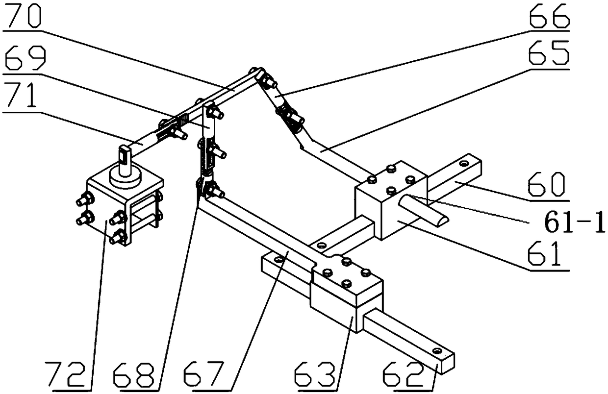
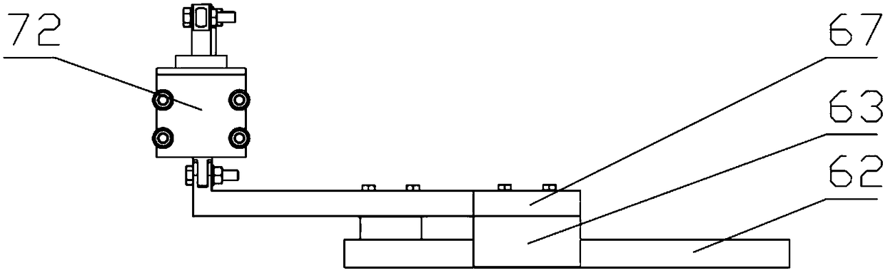
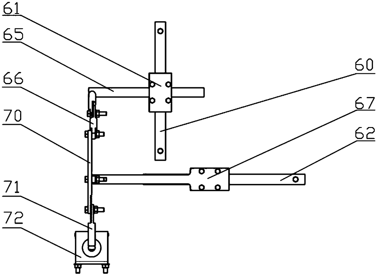
[0019] combine figure 1 , a shift manipulator for an automatic driving robot of the present invention, comprising a first stepping motor, a first slider 61, a first slide rail 60, a first connecting rod 65, a second connecting rod 66, a first swing rod 70, Hand 72, the second stepping motor, the second slide block 63, the second slide rail 62, the third connecting rod 67, the fourth connecting rod 68; the first stepping motor, the second stepping motor, the first The slide rail 60 and the second slide rail 62 are all fixed on the upper end of the casing 1; the first stepping motor is connected with the first slide block 61; the first slide block 61 is driven to move back and forth along the first slide rail 60; A chute 61-1 is provided in the first sli...


PUM


Abstract

The invention provides a gear-shifting manipulator of an autopilot robot, which comprises a first stepping motor, a first slider, a first slide rail, a first link, a second link, a first swing bar, agripper, a second stepping motor, a second slider, a second slide rail, a third link, and a fourth link; The first stepping motor, the second stepping motor, the first slide rail and the second sliderail are fixed on the upper end of the box body; The first stepping motor drives the first slider to move forward and backward along the first slide rail; The third connecting rod is matched with thesliding groove in the first slider and is perpendicular to the sliding direction of the first slider; The lower end of the second connecting rod is connected with the third connecting rod; An upper end of the second connecting rod and a rear end of the first swing rod are connected with each other through a pin shaft; The front end of the first swing lever is connected with the grip; The second stepping motor drives the second slider to slide along the second sliding rail, and the sliding direction is perpendicular to the first slider; The third connecting rod is connected with the second slider; The lower end of the fourth connecting rod is connected with the third connecting rod; An upper end of the fourth connecting rod is connected with the first swing rod through a pin shaft; The manipulator can be adapted to different types of cab and shifting mode.

Description

technical field [0001] The invention belongs to the technical field of driving devices, in particular to a shift manipulator of an automatic driving robot. Background technique [0002] In recent years, more and more people have realized the advantages of unmanned robots and gradually began to study them. Among them, the shifting manipulator of unmanned robots is also our main breakthrough. On the one hand, the shift manipulator of the self-driving robot can accurately complete the shifting action of the vehicle alone, and through computer control, it can cooperate with the mechanical legs to complete the switching between starting and shifting actions. On the other hand, the shifting manipulator of the autonomous driving robot needs to be conveniently controlled, not only to realize the shifting of the car, but also to realize the shifting of other crane cabs, so as to improve the applicability of the unmanned robot. [0003] Chinese patent CN201110359937.4 discloses a shi...

Claims


Application Information

Patent Timeline
Patent Type & Authority Applications(China)
IPC IPC(8): B60K20/02
CPCB60K20/02
Inventor 陈刚许馨瑶王卫东刘炀辉
Owner NANJING UNIV OF SCI & TECH
Why Eureka
Try Eureka