Machine cover hinge high-precision centering and positioning structure

A centering positioning, high-precision technology, applied in the fields of motor vehicles, transportation, and packaging, can solve the problems of no close relationship, limited positioning accuracy, and the inability to achieve optimal positioning. Consistent position and size

Active Publication Date: 2019-01-18
ANHUI JEE AUTOMATION EQUIP CO LTD
View PDF6 Cites 5 Cited by
  • Summary
  • Abstract
  • Description
  • Claims
  • Application Information

AI Technical Summary

Problems solved by technology

Obviously, when the existing split positioning mechanism is used to position the hood hinge, the positioning accuracy is limited by the overall forming accuracy of the cabin; at the same time, the purpose of locating the hood hinge is to realize the matching clearance between the hood, the fender, and the left and right doors. Consistency and elimination of surface differences. The split positioning structure adopted in the prior art uses the existing hole surface of the cabin longitudinal beam as a reference, and is not closely related to the canopy and fenders, so optimal positioning cannot be achieved.

Method used


Image

  • Machine cover hinge high-precision centering and positioning structure
  • Machine cover hinge high-precision centering and positioning structure
  • Machine cover hinge high-precision centering and positioning structure

Examples


Embodiment Construction

[0020] In order to make the purpose, technical solutions and advantages of the embodiments of the present invention clearer, the technical solutions in the embodiments of the present invention will be clearly and completely described below in conjunction with the embodiments of the present invention. Obviously, the described embodiments are part of the present invention Examples, not all examples. Based on the embodiments of the present invention, all other embodiments obtained by persons of ordinary skill in the art without creative efforts fall within the protection scope of the present invention.

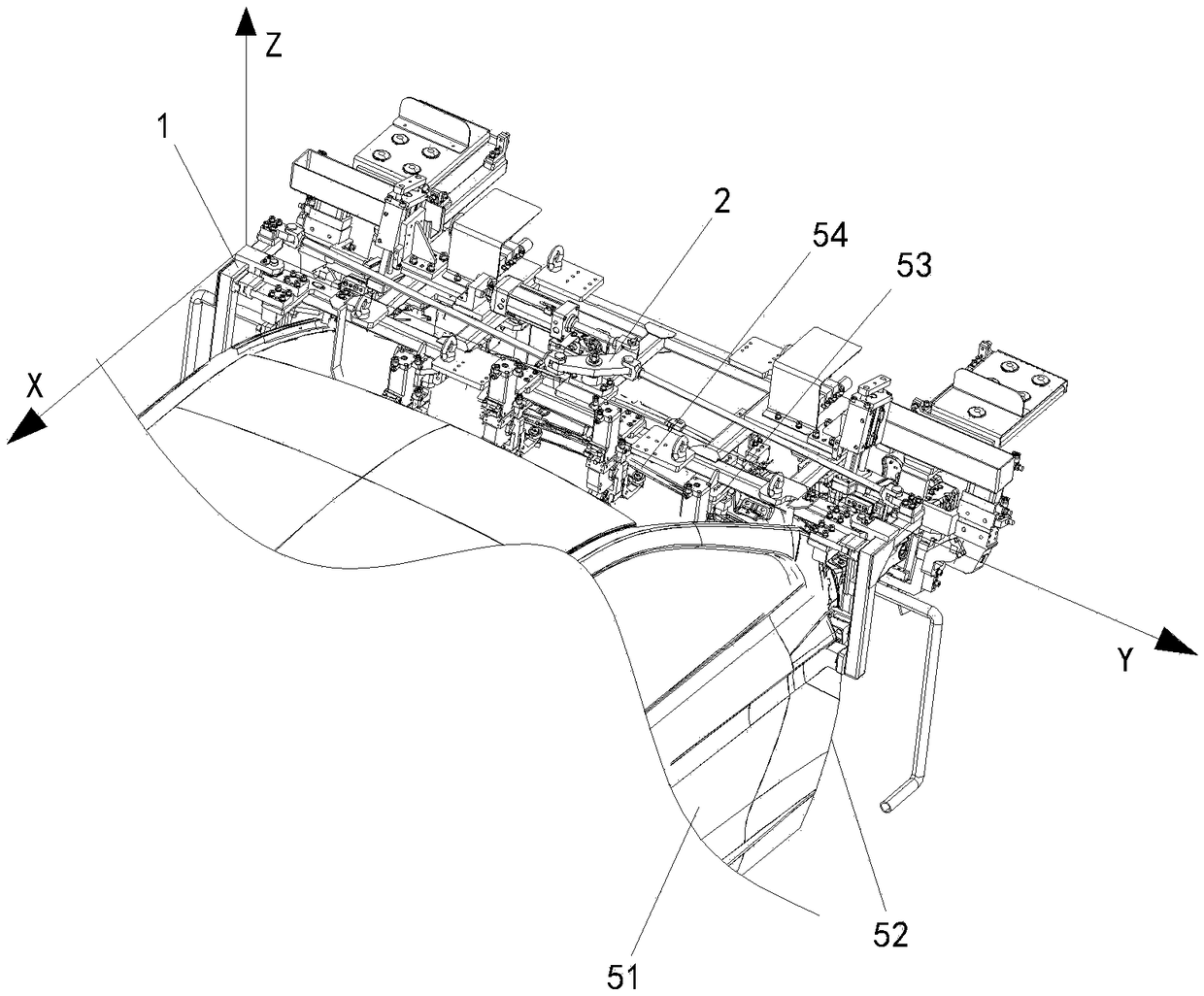
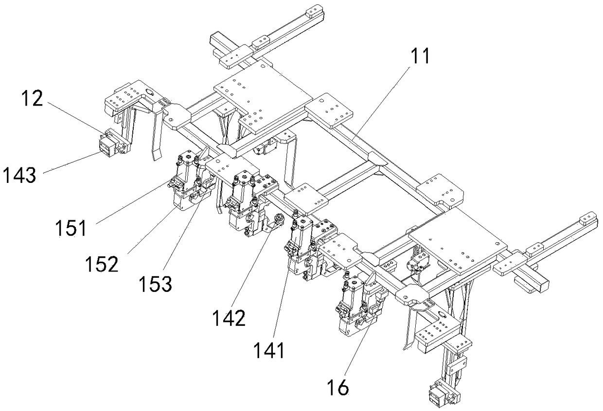
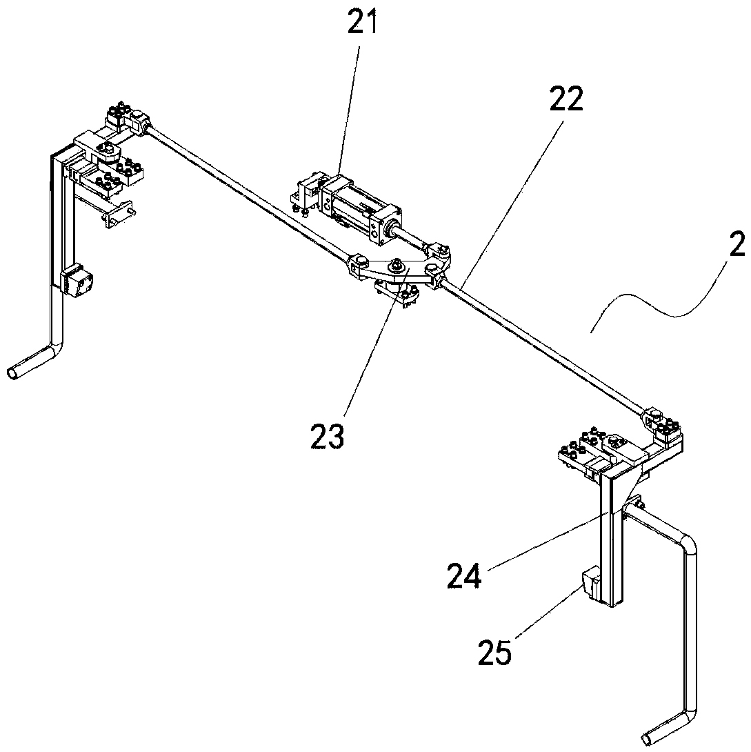
[0021] Such as Figure 1 ~ Figure 3 As shown, the structural relationship is as follows: including the XZ direction positioning mechanism 1 and the Y direction centering mechanism 2, the XZ direction positioning mechanism 1, the Y direction centering mechanism 2 and the hinge positioning cylinder 3 are installed on the installation frame 11, and the Y direction centering mechanis...


PUM


Abstract

The invention discloses a machine cover hinge high-precision centering and positioning structure and relates to the technical field of positioning structures. A Y-direction nylon position block facingthat middle is arrange at both ends of the Y-direction centering mechanism, the two nylon positioning blocks are respectively in close contact with the outer sides of the two front doors of the vehicle, An X-direction nylon position block facing that front side of the vehicle is arrange at both ends of the XZ-direction positioning mechanism, Two cam guides are symmetrically arranged in the middle, two X-direction nylon positioning blocks are respectively close to the rear sides of the two front doors of the vehicle, the two cam guides are close to the rear side of the engine room front uppercasing assembly, and the two ball-head bolts are positioned at the overlap edges directly above the engine room front upper casing assembly. As that front face and the side face of the left and rightvehicle door are directly taken as the positioning reference, when the mount hole on the engine compartment longitudinal beam is taken as the positioning reference of the tooling, the spatial dimension error between the engine compartment longitudinal beam itself and the left and right vehicle doors is reduce, thereby reducing the matching error between the engine cover hinge and the vehicle door,and further reducing the clearance error between the engine cover and the vehicle door.

Description

technical field [0001] The invention relates to the technical field of positioning structures, in particular to a positioning structure for positioning a cover hinge. Background technique [0002] The hood hinge is a common auto part, which is mostly used to connect the engine compartment cover and the body of the car. At present, when the cover hinge is assembled, there are more split-type positioning structures on both sides. The tooling realizes positioning by finding the existing holes and surfaces on the longitudinal beam of the cabin. In addition, most of the existing split-type tooling adopts a positioning pin structure, and the positioning in two directions is realized through the cooperation of pins and holes, and the positioning in the third direction is performed through the structure of the supporting block. Obviously, when the existing split positioning mechanism is used to position the hood hinge, the positioning accuracy is limited by the overall forming accu...

Claims


Application Information

Patent Timeline
Patent Type & Authority Applications(China)
IPC IPC(8): B62D65/02B62D65/06
CPCB62D65/024B62D65/06
Inventor 刘蕾申启乡任玉峰张劲超
Owner ANHUI JEE AUTOMATION EQUIP CO LTD
Why Eureka
Try Eureka