
Hydraulic torque converter which is provided with cooling blade and control oil passage and is capable of lowering working temperature

A technology for hydraulic torque converters and cooling blades, which is applied to belts/chains/gears, fluid transmission devices, mechanical equipment, etc., and can solve problems such as blade surface corrosion, hydraulic transmission oil viscosity damage, and poor cooling effect

Active Publication Date: 2019-01-18
SHENYANG INST OF ENG +1
View PDF20 Cites 0 Cited by
  • Summary
  • Abstract
  • Description
  • Claims
  • Application Information

AI Technical Summary

Problems solved by technology

[0004] In addition, the liquid flowing out of the turbine outlet impacts the stationary guide wheel, which will cause a large axial force on the guide wheel, and the unbalanced axial force will aggravate the damage of the bearing and greatly shorten the service life of the bearing.
At present, the method of reducing the working oil temperature of the hydraulic torque converter is mainly to cool down the working oil, but the cooling effect is too poor. After a long time of work, the hydraulic transmission oil should be replaced regularly, and the viscosity of the hydraulic transmission oil will decrease. It is greatly damaged, and at the same time, the surface of the blade will cause irreversible corrosion. If things go on like this, the blade will not be able to be used, which greatly shortens the service life of the blade
[0005] The current traditional method of offsetting the axial force is mainly to select a suitable bearing to offset the axial load generated by the liquid impacting the guide wheel at the outlet of the high-speed rotating turbine inside the torque converter. It is very complicated, it belongs to an unsteady flow, and the axial load generated is also unsteady, which will make the bearing positioning unreliable and aggravate the bearing damage

Method used


Image

  • Hydraulic torque converter which is provided with cooling blade and control oil passage and is capable of lowering working temperature
  • Hydraulic torque converter which is provided with cooling blade and control oil passage and is capable of lowering working temperature
  • Hydraulic torque converter which is provided with cooling blade and control oil passage and is capable of lowering working temperature

Examples


Embodiment Construction

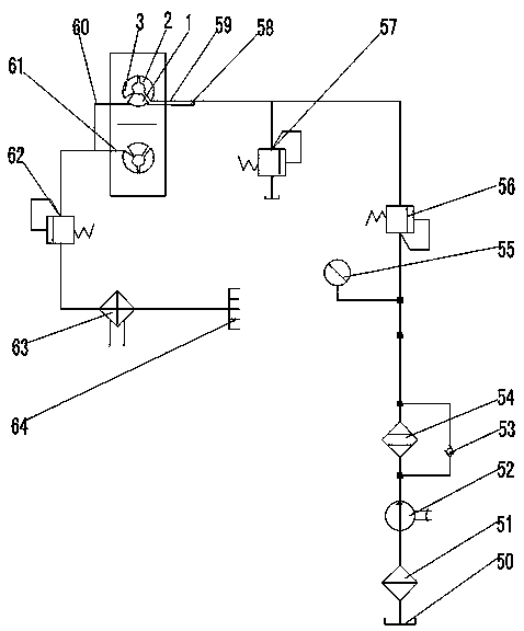
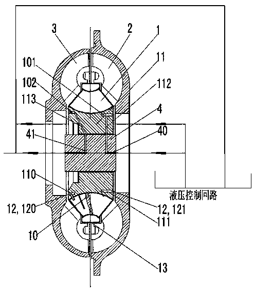
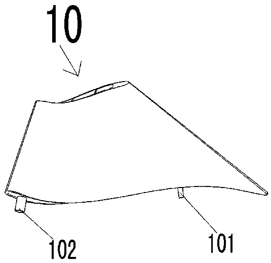
[0022] see Figure 1 to Figure 4 As shown, a hydraulic torque converter with cooling blades and control oil circuit can reduce the working temperature, including guide wheel 1, pump wheel 2, turbine 3, spline shaft 4, cooling circulation oil circuit and hydraulic torque converter Drive circulation oil circuit, guide wheel 1 is placed on spline shaft 4, pump wheel 2 and turbine wheel 3 are respectively placed on both sides of guide wheel 1, cooling circulation oil circuit flows through spline shaft 4 and guide wheel 1 internal cooling flow respectively The transmission circulation oil circuit of the hydraulic torque converter flows through the pump wheel 2, the turbine wheel 3 and the guide wheel 1 respectively;

[0023] The spline shaft 4 is provided with a first oil passage 40 and a second oil passage 41;

[0024] The guide wheel 1 comprises a plurality of guide wheel cooling blades 10, a guide wheel seat 11 (equivalent to the guide wheel outer ring), an oil deflector 12 and...


PUM


Abstract

The invention discloses a hydraulic torque converter which is provided with a cooling blade and a control oil passage and is capable of lowering the working temperature. The hydraulic torque convertercomprises a pump impeller, a guide wheel, a turbine, a spline shaft, a cooling circulating oil passage and a hydraulic torque converter transmission circulating oil passage, the guide wheel is placedon the spline shaft, the pump impeller and the turbine are placed on the two sides of the guide wheel respectively, the cooling circulating oil passage flows through the spline shaft and the guide wheel separately, and the hydraulic torque converter transmission circulating oil passage flows through the pump wheel, the turbine and the guide wheel in sequence; a guide wheel is internally providedwith a runner, a rib plate is placed in the runner to enhance heat dissipation, and axial force needing to be offset in the working process of the hydraulic torque converter is controlled by controlling the pressure difference of the two ends of cooling liquid flowing into the runner; in the working process of the hydraulic torque converter, the temperatures of an outer ring of a working wheel andthe surface of the blade are high, due to the fact that the cooling blade cannot be arranged on a rotating working wheel, the cooling blade is only machined on a stationary guide wheel, then an inletof the runner is formed in the side, close to the pump wheel, of a guide wheel base, and an outlet is formed in the side, close to the turbine, of the guide wheel base.

Description

technical field [0001] The invention relates to the technical field of hydraulic torque converters, in particular to a hydraulic torque converter with cooling blades and a control oil circuit which can reduce the working temperature. Background technique [0002] The hydraulic torque converter is a turbomachinery that relies on fluid kinetic energy to transmit power, and is mainly composed of a pump wheel, a turbine wheel and a guide wheel. When the hydraulic torque converter is working, the working cavity is filled with oil, and the oil flows along the flow path of the working wheel. The pump wheel is connected to the engine, and the rotating blades of the pump wheel push the internal oil to move, converting mechanical energy into liquid energy; then the high-speed oil impacts the turbine blades to make them rotate, and the turbine is connected to the load to convert the liquid energy into mechanical energy; The liquid flowing out of the turbine flows to the fixed guide wh...

Claims


Application Information

Patent Timeline
Patent Type & Authority Applications(China)
IPC IPC(8): F16H41/04F16H41/30
CPCF16H41/04F16H41/30Y02E10/20
Inventor 谭越刘春宝冉子林马文星
Owner SHENYANG INST OF ENG
Learn More