Air valve state monitoring device and method

A state monitoring device and monitoring device technology, applied in valve devices, engine components, mechanical equipment, etc., can solve problems affecting water delivery efficiency, pipe network water hammer, lack of automatic monitoring, etc., to save manual line inspection labor, Extend the service life and avoid the effect of water hammer in the pipe network

Pending Publication Date: 2019-01-18
ZHUZHOU SOUTHERN VALVE
View PDF9 Cites 2 Cited by
  • Summary
  • Abstract
  • Description
  • Claims
  • Application Information

AI Technical Summary

Problems solved by technology

[0002] In order to ensure the safety of water supply on long-distance water pipelines, air valves need to be installed at local high points, slope change sections, and long-distance straight sections of the pipeline to automatically exhaust or enter water according to the situation of pipeline water filling or drainage. Air, the number of air valves installed on long-distance water pipelines is quite large. At present, all kinds of air valves lack automatic monitoring devices for their working status. Network water hammer, even pipe burst and pipe collapse accidents; if you only rely on manual inspection of the pipeline to check whether the air valves are working normally, it is time-consuming, laborious and inefficient

Method used


Image

  • Air valve state monitoring device and method
  • Air valve state monitoring device and method

Examples


Embodiment 1

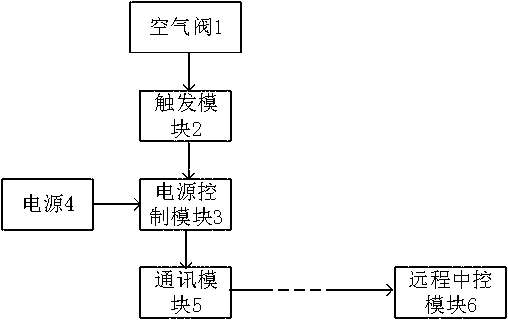
[0020] An air valve working state monitoring device, comprising a power supply 4, a power supply control module 3, a communication module 5, a remote central control module 6, and a trigger module 2; the trigger module 2 is arranged inside the air valve 1, and the power supply 4, the power control module 3 and the The communication module 5 is arranged outside the air valve 1; the input end of the power control module 3 is electrically connected to the power supply 4 and the trigger module 2 respectively, and the output end of the power control module 3 is connected to the communication module, which is used for the power control module 3 to receive the trigger signal and output voltage for communication The module 5 supplies power; a data transmission channel is established between the remote central control module 6 and the communication module 5 for realizing signal communication.

[0021] Exemplarily, the trigger module 2 is specifically a micro switch, and the micro switch...

Embodiment 2

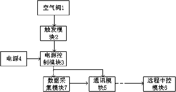
[0032] An air valve working state monitoring device, comprising a power supply 4, a power supply control module 3, a communication module 5, a remote central control module 6, a trigger module 2, and a data acquisition module 7; the trigger module 2 and the data acquisition module 7 are arranged on the air valve 1 Internally, the power supply 4, power supply control module 3 and communication module 5 are arranged outside the air valve 1; the input terminals of the power supply control module 3 are electrically connected to the power supply 4 and the trigger module 2 respectively, and the output terminals of the power supply control module 3 are respectively connected to the communication module and data acquisition Module 7 is used for the power control module 3 to receive the trigger signal and output voltage to supply power to the communication module 5 and the data acquisition module 7; a data transmission channel is established between the remote central control module 6 an...


PUM


Abstract

The invention provides an air valve state monitoring device and method. By arranging the air valve monitoring device, different work states of air discharge, suction, sealing, failure and the like ofair valves on a pipeline or a pipe network can be remotely monitored by a center control unit, if failure happens, the position of a faulty air valve can be displayed in the center control unit, and an alarm is sent out, so that a manager can maintain and overhaul the air valve in time, the manual patrolling work-load is reduced, the service life of the air valve is prolonged, bad accidents, suchas pipe network water hammer, pipe explosion and pipe collapse, are prevented, and smart water management can be easily improved.

Description

technical field [0001] The present invention relates to the technical field of air valves, and more specifically, to an air valve state monitoring device and method. Background technique [0002] In order to ensure the safety of water supply on long-distance water pipelines, air valves need to be installed at local high points, slope change sections, and long-distance straight sections of the pipeline to automatically exhaust or enter water according to the situation of pipeline water filling or drainage. Air, the number of air valves installed on long-distance water pipelines is quite large. At present, all kinds of air valves lack automatic monitoring devices for their working status. Network water hammer, and even pipe burst and pipe collapse accidents; if only rely on manual inspection of the pipeline to check whether the air valves are working normally, it is time-consuming, laborious and inefficient. Contents of the invention [0003] The technical problem to be sol...

Claims


Application Information

Patent Timeline
Patent Type & Authority Applications(China)
IPC IPC(8): F16K37/00
CPCF16K37/0083
Inventor 黄靖桂新春欧立涛刘浩汪庆湘颜梅星
Owner ZHUZHOU SOUTHERN VALVE
Why Eureka
Try Eureka