Automatic lamp-tube light-source-strip attaching device and method

A technology for light source strips and light tubes, which is applied to light sources, lighting devices, semiconductor devices of light-emitting elements, etc., can solve the problems of low production efficiency, inability to mass production, low efficiency of manual sticking, etc., and achieves solutions to low efficiency and production efficiency. high effect

Pending Publication Date: 2019-01-18
中山芯蕊光电科技有限公司
View PDF9 Cites 1 Cited by
  • Summary
  • Abstract
  • Description
  • Claims
  • Application Information

AI Technical Summary

Problems solved by technology

[0003] The purpose of the present invention is to overcome the low efficiency of manual sticking existing in the prior art, and provide an automatic sticking device, which solves the problems of low production efficiency and inability to produce in batches

Method used


Image

  • Automatic lamp-tube light-source-strip attaching device and method
  • Automatic lamp-tube light-source-strip attaching device and method
  • Automatic lamp-tube light-source-strip attaching device and method

Examples


Embodiment 1

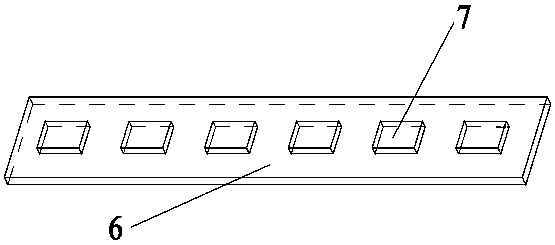
[0030] Such as figure 1 As shown, the light source bar includes an LED lamp bead 7 and an LED carrier 6. The LED carrier 6 can be a common circuit board, or a circuit board with a radiator installed, or an LED lamp directly mounted on a mirror surface metal. Bead 7 vector pattern. The LED lamp bead 7 communicates with the external power supply through the circuit on the carrier and the electrical connector.

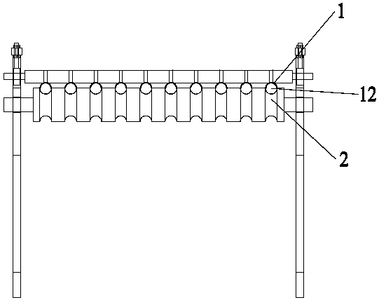
[0031] Such as figure 2 As shown, the curling mechanism includes several guide cylinders 1 and rollers 2, each of which is semi-cylindrical, and the rollers 2 are provided with several circles corresponding to each guide cylinder 1. Arc-shaped grooves, each of the guide cylinders 1 and the arc-shaped grooves on the corresponding rollers 2 form an arc-shaped cavity 12, the rollers 2 are connected with a driving device, and the elastic film passes through the arc-shaped grooves. When the arc-shaped cavity 12 is described, it forms a curl shape.

[0032] The first step ...

Embodiment 2

[0043] A method for automatically pasting strips of light source strips for lamp tubes, comprising using a device for automatically pasting strips for light source strips of light tubes as described in the above-mentioned embodiment 1 and a method for pasting strips, and the method of use includes the following steps:

[0044] Step 1. Set the lamp tube on the first limiting groove 53 in the fixed ferrule 51, and the movable ferrule 52 is driven by the power source to cooperate with the fixed ferrule 51 to form a The first circular limiting groove fixes the lamp tube, and at the same time forms the second circular limiting groove adapted to the shape of the elastic film and the light source bar component;

[0045] Step 2. Manually curl the flattened elastic film into a shape suitable for the arc-shaped cavity 12, and the roller 2 rolls under the action of the driving device to drive the subsequent flattened elastic film to continue to advance. The shaft 2 and the guide cylinder...


PUM


Abstract

The invention discloses a light-source-strip attaching device, and particularly relates to an automatic lamp-tube light-source-strip attaching device and method. An elastic-film reversing tool comprising a circular-truncated-cone-shaped limiting groove and a third circular limiting groove is arranged, the limiting grooves are communicated with each other, an elastic-film curling mechanism is correspondingly arranged at an inlet of the circular-truncated-cone-shaped limiting groove, a lamp-tube positioning mechanism is correspondingly arranged at an outlet of the third circular limiting groove,and a light-source-strip positioning block is arranged at the upper portion of the elastic-film curling mechanism. During working, an elastic film becomes curly through the elastic-film curling mechanism, a light source strip and the curled elastic film are attached through the light-source-strip positioning block and enter the circular-truncated-cone-shaped limiting groove, and the elastic filmand the light source strip are limited to be in a tight cylindrical shape and are conveyed to the lamp tube positioning mechanism for strip attaching. Automatic production including fixing of the lamptube, curling of the elastic film and installing of the light source strip into the lamp tube is achieved, production efficiency is high, and the problems that efficiency of manual strip attaching islow, and automatic batch production cannot be achieved are solved.

Description

technical field [0001] The invention relates to a light source strip sticking device, in particular to a lamp tube light source strip automatic sticking device and a lamp tube light source strip automatic sticking method. Background technique [0002] The existing light source bar has a structure such as figure 1 As mentioned above, it includes the LED carrier and several LED lamp beads arranged on the LED carrier. The method of sticking the strips is manual sticking. Installed in the lamp tube, the efficiency is low, and it cannot be mass-automated. Contents of the invention [0003] The object of the present invention is to overcome the low efficiency of manual sticking existing in the prior art, and provide an automatic sticking device, which solves the problems of low production efficiency and incapable of batch production. [0004] In order to realize the above-mentioned purpose of the invention, the present invention provides the following technical solutions: [...

Claims


Application Information

Patent Timeline
Patent Type & Authority Applications(China)
IPC IPC(8): F21K9/90F21Y115/10
CPCF21K9/90F21Y2115/10
Inventor 陈炜旻
Owner 中山芯蕊光电科技有限公司
Why Eureka
Try Eureka