
Air duct indoor machine and air conditioning unit

A technology of air duct indoor unit and air outlet, which is applied in air-conditioning system, space heating and ventilation, household heating and other directions, can solve the problem of poor dustproof effect of air duct indoor unit.

Pending Publication Date: 2019-01-18
GREE ELECTRIC APPLIANCES INC
View PDF0 Cites 0 Cited by
  • Summary
  • Abstract
  • Description
  • Claims
  • Application Information

AI Technical Summary

Problems solved by technology

[0005] The embodiment of the present invention provides an air duct indoor unit and an air conditioning unit to solve the technical problem of the poor dustproof effect of the air duct indoor unit in the prior art

Method used


Image

  • Air duct indoor machine and air conditioning unit
  • Air duct indoor machine and air conditioning unit
  • Air duct indoor machine and air conditioning unit

Examples


Embodiment Construction

[0026] In order to make the object, technical solution and advantages of the present invention clearer, the present invention will be described in further detail below in conjunction with the embodiments and accompanying drawings. Here, the exemplary embodiments and descriptions of the present invention are used to explain the present invention, but not to limit the present invention.

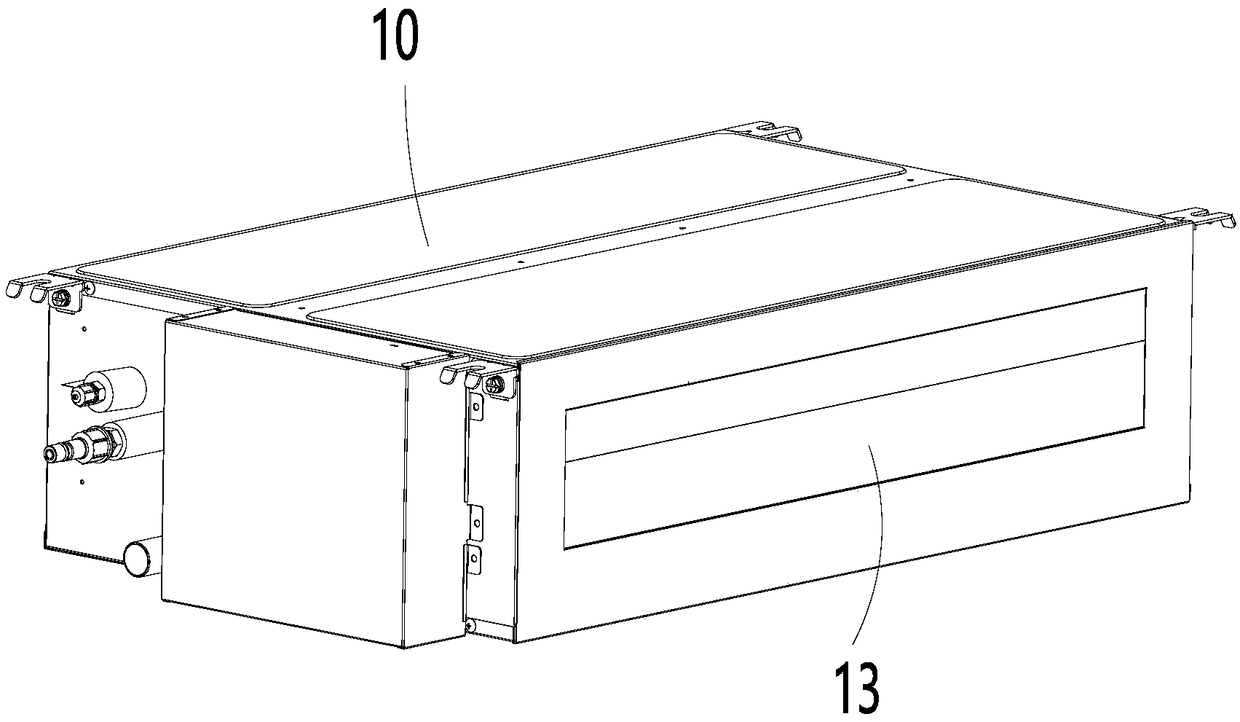
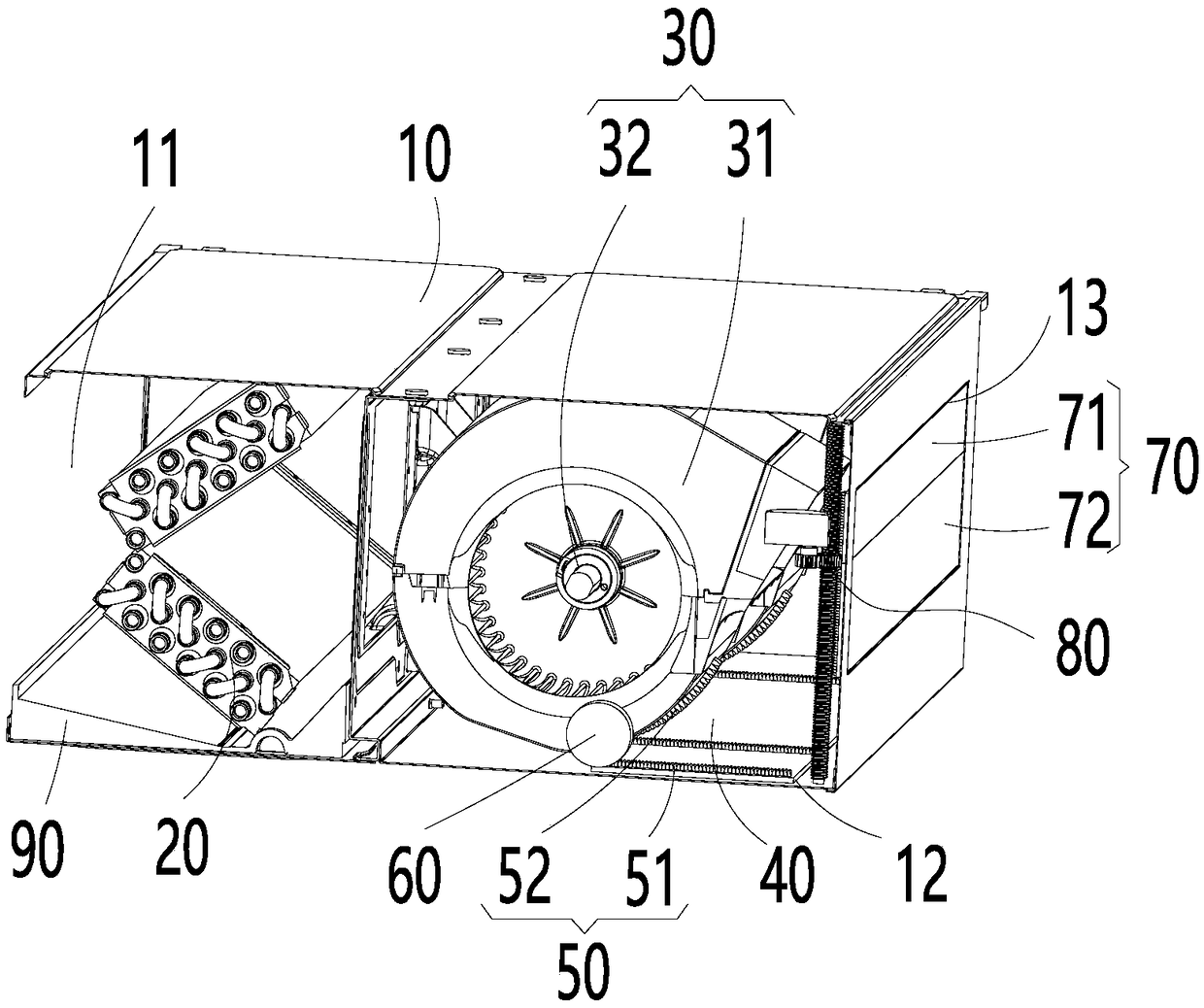
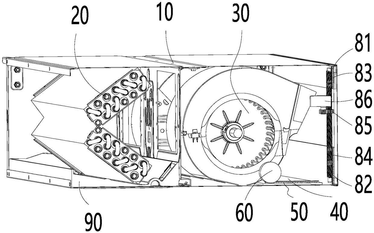
[0027] figure 1 and figure 2 An embodiment of the air duct indoor unit of the present invention is shown, and the air duct indoor unit includes a main casing 10 , a heat exchanger 20 , an air supply component 30 and a first air outlet baffle 40 . A cavity is formed inside the main housing 10 , and an air inlet 11 connected to the cavity and at least two air outlets are opened on the main housing 10 . The heat exchanger 20 is arranged in the cavity and is located at the air inlet 11, the air supply part 30 is rotatably arranged in the cavity and is located at the air outlet, the air inlet end...


PUM


Abstract

The invention provides an air duct indoor machine and an air conditioning unit. The air duct indoor machine comprises a main shell, a heat exchanger, an air supply component and a first air port baffle. A cavity is formed in the main shell, and an air inlet and at least two air outlets connected with the cavity are arranged on the main shell. The first air port baffle is movably arranged on the air outlet and is connected with the air supply component through the linkage mechanism. When an air supply part rotates to the air outlet, the first air port baffle is driven to open the air outlet through the linkage mechanism, when the air supply part rotates to the other air outlets, the first air port baffle is driven to close and open the air outlet through the linkage mechanism. The air supply part is linked with the first air port baffle through the linkage mechanism, so that no additional driving mechanism is needed to set for driving the first air port baffle to move, meanwhile, the air supply part and the first air port baffle can control the opening and closing of the air outlet more timely and conveniently.

Description

technical field [0001] The invention relates to the technical field of air-conditioning equipment, in particular to an air duct indoor unit and an air-conditioning unit. Background technique [0002] At present, the air outlet direction of most air duct indoor units is single, or the air outlet is in the forward direction, or the air outlet is in the downward direction. This type of air outlet is too simple to meet the special needs of some users, and the air outlet direction of the air duct indoor unit cannot be selected. [0003] When the air outlet direction can be freely selected, the requirements for the diversity and comfort of the air outlet of the unit can be greatly satisfied. An improved air duct indoor unit has appeared on the market. The air duct indoor unit includes two air outlets. By rotating the volute, the air outlet end of the volute can select an air outlet to discharge air. [0004] The air outlet of the above-mentioned air duct indoor unit is continuou...

Claims


Application Information

Patent Timeline
IPC IPC(8): F24F1/0011F24F13/10
CPCF24F1/0014F24F13/10
Inventor 李小芬邓朝胜李功瑞
Owner GREE ELECTRIC APPLIANCES INC
Learn More