A sub-block vibration-damping rotor

A block-type, rotor technology, applied in the direction of magnetic circuit rotating parts, magnetic circuit shape/style/structure, etc., can solve problems such as loud noise vibration, no vibration-damping structure, difficult to design and realize vibration-damping structure, etc. To achieve the effect of increasing torque

Pending Publication Date: 2019-01-18
WOLONG ELECTRIC GRP CO LTD
View PDF0 Cites 6 Cited by
  • Summary
  • Abstract
  • Description
  • Claims
  • Application Information

AI Technical Summary

Problems solved by technology

[0002] The rotors of low-power motors currently used, such as IPM rotors (rotors of embedded permanent magnet synchronous motors), generally do not have a vibration-damping structure. The main reason is that the motor rotor adopts an integrated iron core structure, which makes it difficult to design and implement a vibration-damping structure.
Therefore, while the IPM rotor structure brings greater power density to the motor, it also produces greater noise and vibration

Method used


Image

  • A sub-block vibration-damping rotor
  • A sub-block vibration-damping rotor
  • A sub-block vibration-damping rotor

Examples


Embodiment Construction

[0024] The following description is only for disclosing the present invention to enable those skilled in the art to practice the present invention. The embodiments in the following description are only examples, and those skilled in the art can think of other obvious modifications. The basic principles of the invention defined in the following description can be applied to other embodiments, variations, improvements, equivalents and others without departing from the spirit and scope of the invention.

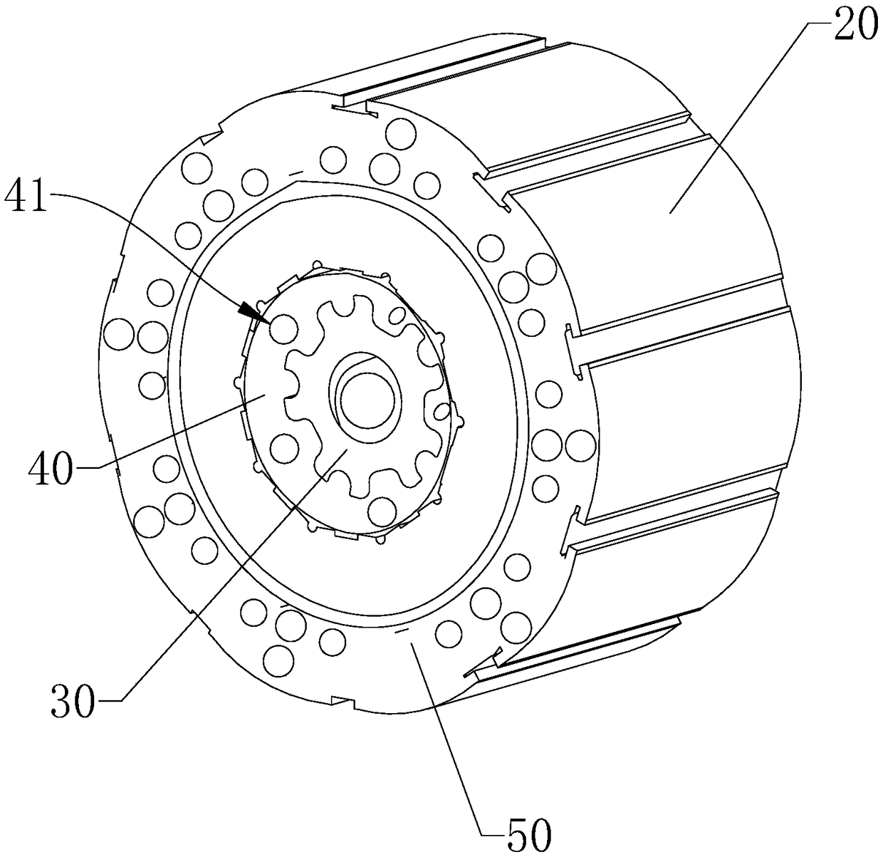
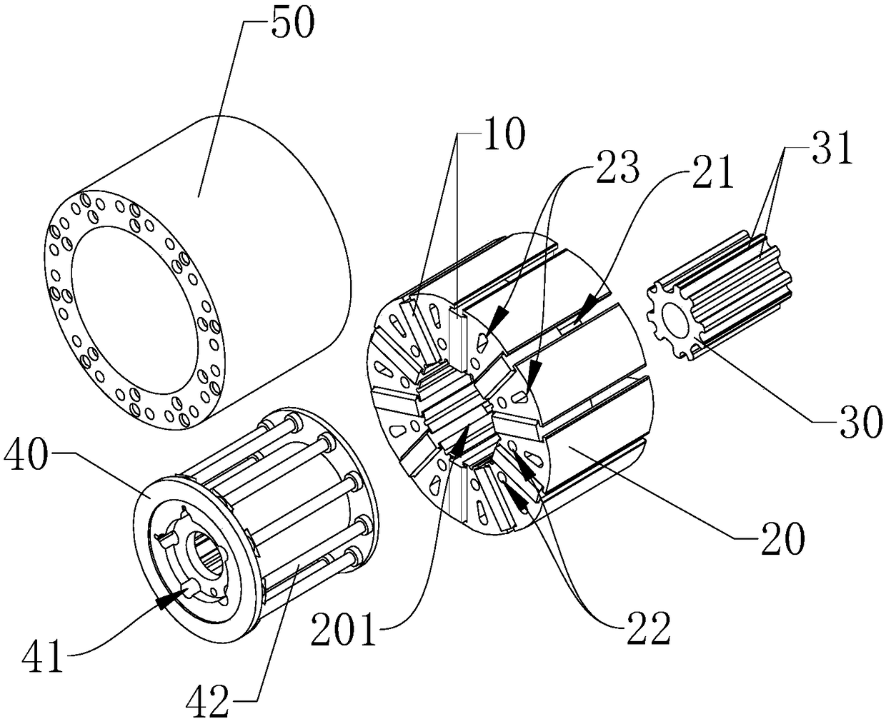
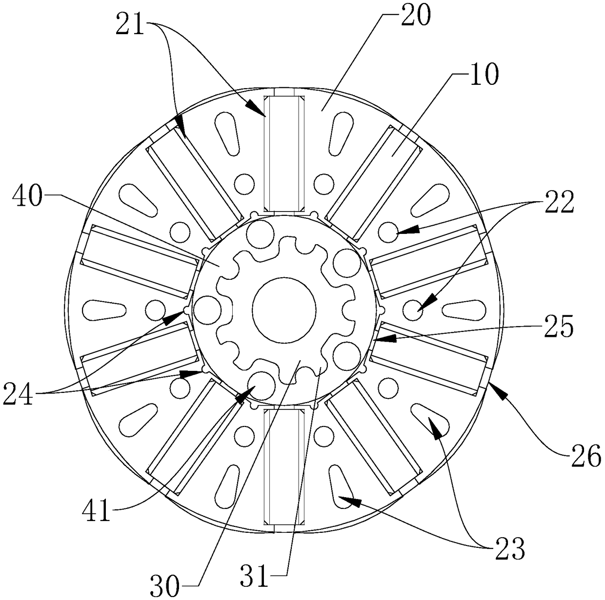
[0025] Such as figure 1 As shown, the present invention provides a block-type vibration-damping rotor suitable for motors. The block-type vibration-damping rotor has a vibration-damping structure to achieve the effect of vibration reduction and noise reduction. Specifically, the segmented damping rotor includes a magnet 10 , an outer iron core 20 , an inner iron core 30 and an elastic glued portion 40 .

[0026] The magnet 10 adopts a tile-shaped magnet, also called a magnetic...


PUM


Abstract

A sub-block vibration-damping rotor includes a magnet, an outer core, an inn core, an engagement portion, and an elastic bonding portion. The outer iron core is provided with a through channel, a magnetic groove, a plurality of positioning gluing holes and a reinforcing hole which penetrate the outer iron core in the axial direction. The magnet is inserted in the magnetic slot, and the inner coreis embedded in the channel inside the outer core. A PBT material is injected into that reinforcing hole, and the PBT material is distributed at both ends of the outer iron core along the reinforcing hole to form a joint part, so that the out iron core and the magnet are molded into a one-time molded product by one-time injection molding of the PBT material. An elastic glue is injected into the positioning glue hole and an elastic glue part is integrally formed at both ends of the outer iron core and the inner iron core and between the outer iron core and the inner iron core respectively, so that the primary molded product and the inner iron core are secondary molded into a secondary molded product by the elastic glue. The elastic glue can cushion the force between the outer core and the inner core, so as to play the effect of vibration and noise reduction.

Description

technical field [0001] The invention relates to the technical field of motors, in particular to a segmented damping rotor. Background technique [0002] The rotors of low-power motors currently used, such as IPM rotors (rotors of embedded permanent magnet synchronous motors), generally do not have a vibration-damping structure. The main reason is that the motor rotor adopts an integrated iron core structure, which makes it difficult to design and implement a vibration-damping structure. . Therefore, while the IPM rotor structure brings greater power density to the motor, it also produces greater noise and vibration. The problem of equipment failure and consumption caused by the vibration of the rotor is becoming more and more prominent. How to reduce the vibration of the motor rotor has become a new topic. Contents of the invention [0003] The purpose of the present invention is to provide a segmented damping rotor, which solves the problem that the rotor in the prior a...

Claims


Application Information

Patent Timeline
IPC IPC(8): H02K1/22H02K1/27
CPCH02K1/22H02K1/27
Inventor 王龙杜荣法玉村周平丁德亮严浩波赵新超李贻伟
Owner WOLONG ELECTRIC GRP CO LTD
Why Eureka
Try Eureka