
Power supply method, device and system

A power supply system and power supply circuit technology, applied in the field of communication, can solve the problems of reducing the design efficiency and design flexibility of the main circuit power supply circuit, and the design of the main transformer is complicated, so as to improve the design flexibility and solve the power supply problem.

Pending Publication Date: 2019-01-18
ZTE CORP
View PDF0 Cites 1 Cited by
  • Summary
  • Abstract
  • Description
  • Claims
  • Application Information

AI Technical Summary

Problems solved by technology

[0006] Embodiments of the present invention provide a power supply method, device, and system to at least solve the problem of complicating the design of the main transformer by adding auxiliary windings to the transformer of the main power supply circuit to supply power to the control circuit in the anti-backfeed circuit in the related art. The problem of reducing the design efficiency and design flexibility of the main power supply circuit

Method used


Image

  • Power supply method, device and system
  • Power supply method, device and system
  • Power supply method, device and system

Examples


Embodiment 1

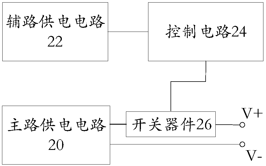
[0040] According to an embodiment of the present invention, a power supply system is provided, which is mainly used to solve the power supply problem of a control circuit in an anti-backfeed circuit of a redundant power supply system. figure 2 is a schematic structural diagram (1) of the power supply system according to Embodiment 1 of the present invention. Such as figure 2 As shown, the power supply system provided in this embodiment includes:

[0041] Main road power supply circuit 20, auxiliary road power supply circuit 22, switch device 26, control circuit 24, wherein, auxiliary road power supply circuit 22, is connected with control circuit 24, is used to provide power supply voltage for control circuit 24; Control circuit 24, via switch device 26 It is connected with the main power supply circuit 20 and is used to control the on and off of the switching device 26 .

[0042] Through this embodiment, a main power supply circuit 20, an auxiliary power supply circuit 22...

Embodiment 2

[0055] In order to better understand the technical solution of the present invention, this embodiment also provides a power supply method, which is applied to the above power supply system, and the descriptions that have already been made will not be repeated here. Figure 4 is a flowchart of a power supply method according to Embodiment 2 of the present invention. Such as Figure 4 As shown, the power supply method of this embodiment includes:

[0056] S402, the control circuit receives the power supply voltage provided by the auxiliary power supply circuit connected to the control circuit;

[0057] S404, the control circuit controls the switch device to be turned on and off, wherein the switch device is connected to the control circuit and the main power supply circuit.

[0058] Through the power supply method of this embodiment, the control circuit receives the power supply voltage provided by the auxiliary power supply circuit connected to the control circuit; the contro...

Embodiment 3

[0072] In order to better understand the technical solutions in the embodiments of the present invention, this embodiment uses several specific examples to specifically describe the circuit structure in the switch control circuit or switch control module, auxiliary circuit power supply circuit or auxiliary circuit power supply module in the above embodiments. illustrate.


PUM


Abstract

The invention provides a power supply method, a device and a system, wherein the power supply system comprises a main circuit power supply circuit, an auxiliary circuit power supply circuit, a controlcircuit and a switching device, wherein, the auxiliary circuit power supply circuit is connected with the control circuit and used for supplying a power supply voltage to the control circuit; The control circuit is connected with the main circuit power supply circuit via the switching device, and is used for controlling the on / off of the switching device. The adoption of that technical scheme, ina related art, the auxiliary winding is added to the transformer of the main circuit power supply circuit to supply power to the control circuit in the anti-backflow circuit, As a result, the transformer design of the main circuit power supply circuit is complicated, which is not conducive to the problem of flexible design and optimization efficiency of the transformer, and can effectively solvethe power supply problem of the control circuit of the anti-backflow circuit, at the same time, the design flexibility of the main circuit power supply circuit is improved, which is conducive to the efficiency optimization of the main circuit design.

Description

technical field [0001] The present invention relates to the communication field, in particular, to a power supply method, device and system. Background technique [0002] The redundant power supply system is a highly reliable power supply system. The power supply system is composed of multiple power supply modules connected in parallel. It is mostly used in servers, computer room systems and other equipment. When the power supply current is reversed and damaged, an anti-reverse circuit is designed at the output high voltage end, that is, an ORING circuit, and a switching device and a control part are added at the output high voltage end. When a module in the parallel power supply is abnormal, the control circuit Control the timely disconnection of switching devices to realize the function of preventing current backfeeding. [0003] figure 1 It is a structural schematic diagram of an anti-backfeed circuit in the related art. Such as figure 1 As shown, the anti-backfeed ci...

Claims


Application Information

Patent Timeline
IPC IPC(8): H02M1/096
CPCH02M1/096
Inventor 陈长青蒙杰成丘廷廷
Owner ZTE CORP
Features
  • Generate Ideas
  • Intellectual Property
  • Life Sciences
  • Materials
  • Tech Scout
  • Unparalleled Data Quality
  • Higher Quality Content
  • 60% Fewer Hallucinations
Learn More