Analysis apparatus and focusing method
An analysis device and a technology for the direction of the optical axis, applied in the direction of analysis materials, image analysis, measurement devices, etc., can solve the problems of low focus accuracy, low contrast, discomfort, etc., and achieve the effect of high focus accuracy
- Summary
- Abstract
- Description
- Claims
- Application Information
AI Technical Summary
Problems solved by technology
Method used
Image
Examples
no. 1 approach
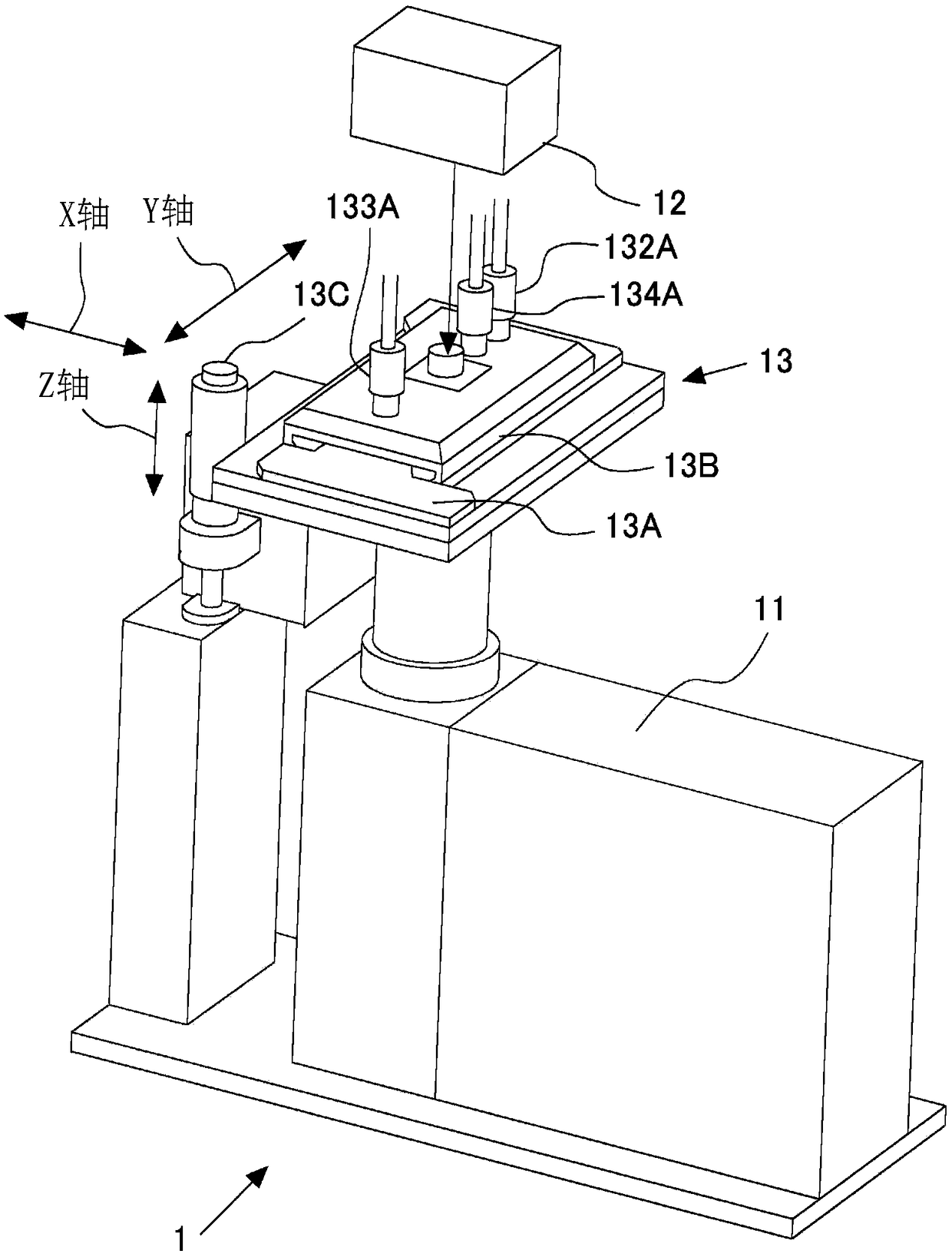
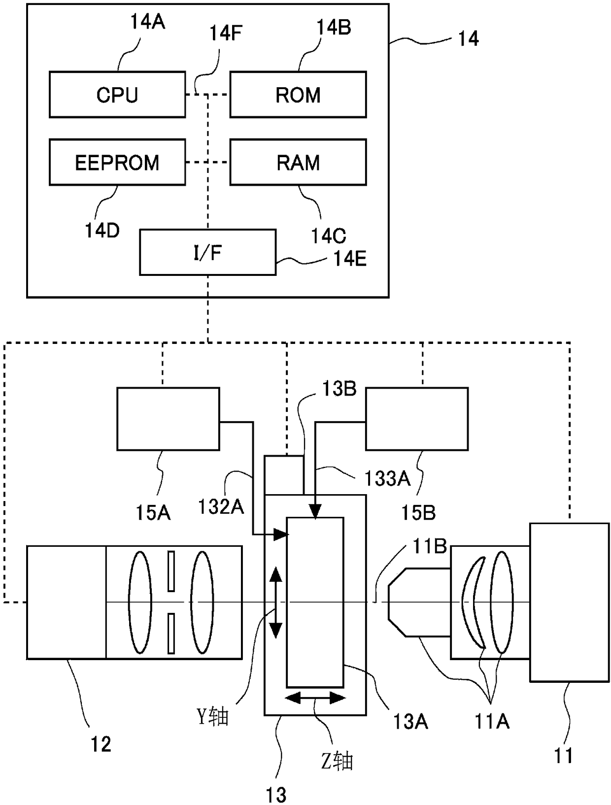
[0028] figure 1 It is a diagram showing a schematic configuration of the imaging device 1 of the first embodiment. The imaging device 1 images, for example, urine as a sample, and is used as an analysis device for analyzing, for example, formed components in urine by analyzing the imaged images. However, the imaging device 1 can also be applied to the analysis of formed components in liquid samples other than urine, such as cells and body fluids.
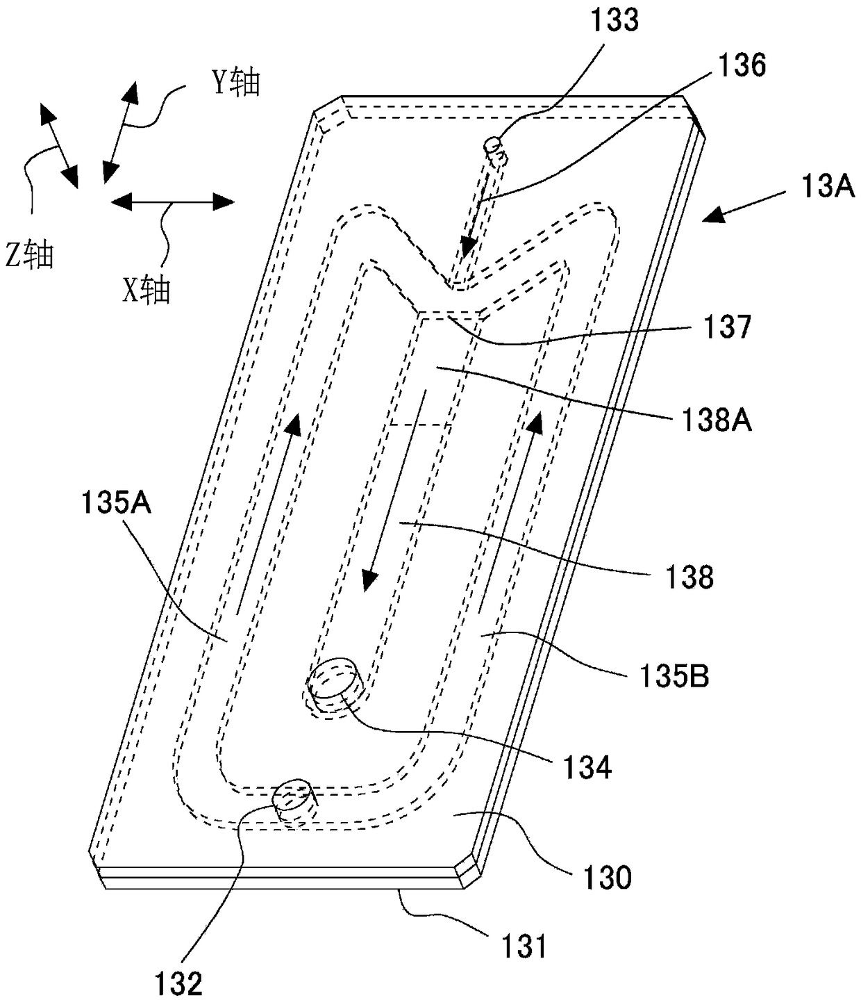
[0029] The imaging device 1 has a camera 11 for imaging a sample, a light source 12 for imaging, and a flow cell unit 13 . The flow cell unit 13 has a stage 13B on which a flow cell 13A through which a sample flows is fixedly arranged. The flow cell 13A is also detachable with respect to the stage 13B. Additionally, the figure 1 In the illustrated imaging device 1 , the longitudinal direction is defined as the X-axis direction in the rectangular coordinate system, the width direction is defined as the Y-axis direction, and the h...
no. 2 approach
[0089]In the second embodiment, focus point determination processing is different from that in the first embodiment. Other devices, controls, and the like are the same as those of the first embodiment, and thus description thereof will be omitted. Here, regarding the focal point determination processing described in the first embodiment, the processing is simple and the calculation speed is increased, but the robustness against images with a low signal-to-noise ratio is low. Therefore, in the second embodiment, the robustness is improved by comparing the inside and outside of the mask image.
[0090] Figure 11 It is a diagram for explaining focus point determination processing. The creation of the mask image 32 , the creation of the blurred image 33 , and the creation of the difference image 34 are the same as those in the first embodiment. In addition, the following will Figure 11 The range corresponding to the covered range (blackened range) in the mask image 32 is cal...
PUM
 Abstract
Description
Claims
Application Information
 - R&D
- Intellectual Property
- Life Sciences
- Materials
- Tech Scout
- Unparalleled Data Quality
- Higher Quality Content
- 60% Fewer Hallucinations
Browse by: Latest US Patents, China's latest patents, Technical Efficacy Thesaurus, Application Domain, Technology Topic, Popular Technical Reports.
© 2025 PatSnap. All rights reserved.Legal|Privacy policy|Modern Slavery Act Transparency Statement|Sitemap|About US| Contact US: help@patsnap.com


