Eureka AIR delivers breakthrough ideas for toughest innovation challenges, trusted by R&D personnel around the world.

Transmission device applied to printing device, transmission system and printing device

A technology of printing equipment and transmission device, which is applied in the direction of printing device, inking device, printing, etc., and can solve the problem of complex coordination of carbon belt conveying and other problems

Pending Publication Date: 2019-01-22
XIAMEN HANIN ELECTRONICS TECH CO LTD
View PDF0 Cites 1 Cited by
  • Summary
  • Abstract
  • Description
  • Claims
  • Application Information

AI Technical Summary

Problems solved by technology

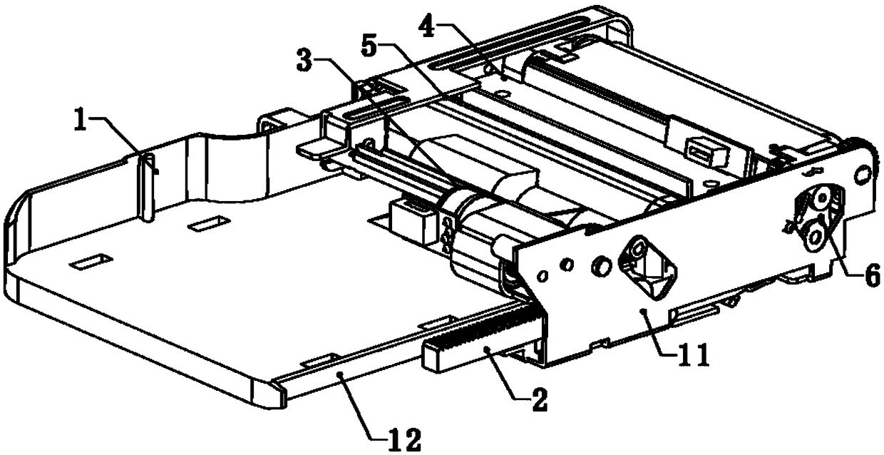
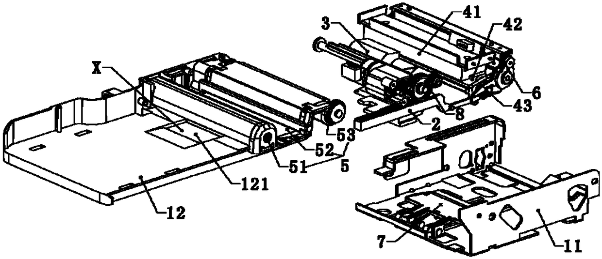
[0003] The present invention provides a transmission device, transmission system and printing equipment applied to printing equipment, aiming at improving the problem of complex coordination between the ribbon conveying, printing unit and pick-up roller in the existing printing equipment

Method used


Image

  • Transmission device applied to printing device, transmission system and printing device
  • Transmission device applied to printing device, transmission system and printing device
  • Transmission device applied to printing device, transmission system and printing device

Examples


Embodiment Construction

[0032] In order to make the purpose, technical solutions and advantages of the embodiments of the present invention clearer, the technical solutions in the embodiments of the present invention will be clearly and completely described below in conjunction with the accompanying drawings in the embodiments of the present invention. Obviously, the described embodiments It is some embodiments of the present invention, but not all of them. Based on the implementation manners in the present invention, all other implementation manners obtained by persons of ordinary skill in the art without creative efforts fall within the protection scope of the present invention. Accordingly, the following detailed description of the embodiments of the invention provided in the accompanying drawings is not intended to limit the scope of the claimed invention, but merely represents selected embodiments of the invention. Based on the implementation manners in the present invention, all other implement...


PUM


Abstract

The invention relates to a transmission device applied to a printing device. The transmission device comprises a main body, a meshing portion, a first linkage portion, a second linkage portion, a third linkage portion and a fourth linkage portion; the main body is connected with the frame of the printing device, and can move reciprocally and linearly along the conveying direction of a recording medium under the action of a driving force; the meshing portion is formed on a side edge of the main body and is in meshed connection with the gear of the driving device; the first linkage portion protrudes upward from the surface of the upper portion of the main body and is in linkage connection with the rubber roller bracket of the printing device when the main body moves to a first linkage position along a first direction, so that the rubber roller bracket can be made to lift; the second linkage portion protrudes toward the output direction of the recording medium from the front end of the meshing portion, and is in linkage connection with the rubber roller bracket when the main body moves to a second interlocking position along the reverse direction of the first direction, so that the rubber roller bracket can be made to descend; the third linkage portion is formed on the side edge of the main body and is in linkage connection with the pick-up roller bracket of the printing device soas to make the pick-up roller bracket lift; and the fourth linkage portion is formed on the side edge of the main body and is in linkage connection with the pick-up roller bracket so as to make the pick-up roller bracket descend.

Description

technical field [0001] The invention relates to the technical field of printers, in particular, to a transmission device and a transmission system applied to printing equipment and printing equipment. Background technique [0002] Most printers are used in offices or homes. There are many types of printers, including inkjet, thermal, thermal transfer, electrostatic and other printers according to the technology used. Wherein, the thermal transfer printing equipment needs to use a carbon ribbon cassette, and the carbon ribbon cassette includes a supply shaft, a recovery shaft and a carbon ribbon whose two ends are connected to the two shafts. It is very important to carry out the transmission of the pick-up roller, the printing unit and the carbon belt transport in an orderly manner in the micro-equipment. The existing transmission structure coordinates the above work through the cam structure and the switching mechanism, which has a large space occupation ratio and the carbo...

Claims


Application Information

Patent Timeline
Patent Type & Authority Applications(China)
IPC IPC(8): B41J29/38B41J33/14B41J2/325
CPCB41J29/38B41J2/325B41J33/14
Inventor 不公告发明人
Owner XIAMEN HANIN ELECTRONICS TECH CO LTD
Why Eureka
Eureka Blog
Learn More