Piezoelectric-Solenoid Double Valve Electronically Controlled Injector

An electronically controlled fuel injection and fuel injector technology, which is applied to fuel injection devices, machines/engines, charging systems, etc., can solve the problems of single working mode, poor working reliability, difficult to flexibly adjust the boost ratio, etc.

Active Publication Date: 2020-12-25
HARBIN ENG UNIV
View PDF5 Cites 0 Cited by
  • Summary
  • Abstract
  • Description
  • Claims
  • Application Information

AI Technical Summary

Problems solved by technology

[0003] The pressurized electronically controlled fuel injector overcomes the problem that the traditional mechanical fuel injector's fuel injection law is restricted by the shape of the cam, and realizes the flexible and controllable fuel injection timing, etc., and also has the effect of providing high injection pressure and fast response speed , with high control accuracy. However, the existing booster electronically controlled fuel injector has a single working mode, and it is difficult to flexibly adjust the boost ratio. For the booster electronically controlled injector controlled by a single valve, once If the solenoid valve fails, the entire fuel injector will not work normally, which will easily cause adverse consequences and poor working reliability

Method used


Image

  • Piezoelectric-Solenoid Double Valve Electronically Controlled Injector
  • Piezoelectric-Solenoid Double Valve Electronically Controlled Injector
  • Piezoelectric-Solenoid Double Valve Electronically Controlled Injector

Examples


Embodiment Construction

[0021] The present invention is described in more detail below in conjunction with accompanying drawing example:

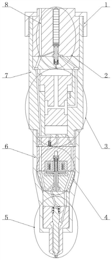
[0022] combine Figure 1-5 , the piezoelectric-electromagnetic dual-valve electronically controlled fuel injector of the present invention includes a fuel injector head 1, a boost control valve 2, a boost piston 3, a fuel injection control valve 4, a nozzle 5, a tight cap 6 and a fuel injector body 7, the injector head 1 is installed on the injector body 7, the booster control valve 2, the booster piston 3, the fuel injection control valve 4 and the nozzle 5 are installed in the injector body 7 sequentially from top to bottom, The tight cap 6 is fastened together with the fuel injector body 7 by threads.

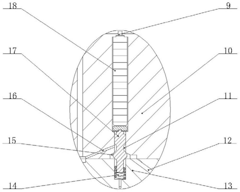
[0023] The boost control valve 2 is installed in the fuel injector body 7, and the boost control valve 2 includes an electrical connector 9, an upper valve seat 10 of the boost control valve, a lower valve seat 13 of the boost control valve, a reset spring 14 o...


PUM


Abstract

The invention aims at providing a piezoelectric-electromagnetic bivalve electronic fuel injector. The piezoelectric-electromagnetic bivalve electronic fuel injector comprises a fuel injector head, a booster control valve, a booster piston, a fuel injection control valve, a nozzle, a cap nut and a fuel injector body. The pressurization process and the fuel injection process are controlled by a piezoelectric crystal and an electromagnetic valve respectively, so that the fuel injection process of the piezoelectric-electromagnetic bivalve electronic fuel injector is not restricted by the pressurization process; therefore, the piezoelectric-electromagnetic bivalve electronic fuel injector can work in a non-pressurization mode and a pressurization mode, injection is carried out according to therail pressure in the non-pressurization mode, ultrahigh-pressure injection is carried out in the pressurization mode, flexible adjustment of the pressure ratio can be achieved by changing the controlstrategy of the booster control valve in the pressurization mode, the reliability is higher, and the application range is wider. By means of the fuel injection control valve, the piezoelectric-electromagnetic bivalve electronic fuel injector can achieve micro-dynamic fuel return, the fuel return amount is greatly reduced, the response speed of a needle valve is increased, and the power performanceand economical efficiency of a diesel engine are effectively improved.

Description

technical field [0001] The invention relates to a fuel system, in particular to a marine diesel engine fuel system. Background technique [0002] The electronically controlled high-pressure common rail fuel injection system is the most promising control system. The high-pressure common rail fuel injection system is the core component of the diesel engine and plays a vital role in reducing diesel engine emissions. The future development of the diesel engine fuel injection system will show high Injection pressure, fuel injection volume and fuel injection schedule can be flexibly controlled. With the increasing energy crisis and environmental pollution, the improvement of diesel fuel injection system has been paid much attention. [0003] The pressurized electronically controlled fuel injector overcomes the problem that the traditional mechanical fuel injector's fuel injection law is restricted by the shape of the cam, and realizes the flexible and controllable fuel injection ...

Claims


Application Information

Patent Timeline
Patent Type & Authority Patents(China)
IPC IPC(8): F02M47/02F02M51/06F02M61/10F02M61/16F02M61/18F02M63/00
CPCF02M47/027F02M51/061F02M61/10F02M61/16F02M61/18F02M63/0026
Inventor 范立云兰奇付立洲白云
Owner HARBIN ENG UNIV
Why Eureka
Try Eureka