V belt wheel for skid resistance by centrifugal force
What is Al technical title?
Al technical title is built by PatSnap Al team. It summarizes the technical point description of the patent document.
A technology of V-pulley and centrifugal force, which is applied to belts/chains/gears, components with teeth, portable lifting devices, etc., can solve problems such as slipping and friction reduction, reduce the probability of slipping, and improve Stability, friction-increasing effect
Inactive Publication Date: 2019-01-22
刘轩佑
View PDF0 Cites 1 Cited by
Summary
Abstract
Description
Claims
Application Information
AI Technical Summary
This helps you quickly interpret patents by identifying the three key elements:
Problems solved by technology
Method used
Benefits of technology
Problems solved by technology
[0005] In order to solve the above-mentioned problems, the present invention provides a V-belt pulley that utilizes centrifugal force to prevent slipping, so as to solve the problem of slippage caused by the reduction of friction between the V-belt working surface and the V-belt pulley when the existing V-belt pulley rotates at high speed. The problem of phenomena
Method used
Image
Click on the blue label to locate the original text in one second.
Reading with bidirectional positioning of images and text.
Examples
Embodiment
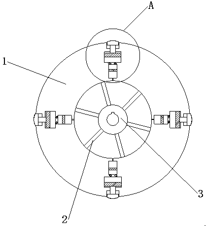
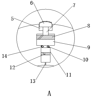
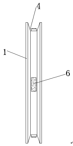
[0025] as attached figure 1 to attach Figure 4 Shown:
[0026] The present invention provides a V-belt pulley that utilizes centrifugal force to prevent slipping, including a rim 1, a spoke 2, a hub 3, a V-belt groove 4, an anti-slip chamber 5, an anti-slip block 6, a connecting rod 7, a connecting rod piston 8, and a movable chamber 9 , the first relief valve 10, the hydraulic cylinder 11, the hydraulic cylinder piston 12, the air hole 13, the second relief valve 14, the inner side of the wheel rim 1 is fixedly connected with the wheel spoke 2, and the other end of the wheel spoke 2 is fixedly connected with the wheel hub 3, the wheel The outer periphery of the rim 1 is provided with a V-belt groove 4, and the bottom of the V-belt groove 4 is provided with an anti-slip cavity 5, which is located inside the rim 1, and an anti-slip block 6 is arranged inside the anti-slip cavity 5, and the bottom of the anti-slip block 6 is fixed Connected with a connecting rod 7, the other ...
PUM
Abstract
The invention provides a V belt wheel for skid resistance by centrifugal force. The V belt wheel comprises a wheel flange, a wheel arm, a wheel hub, a V belt groove, an anti-skid cavity, an anti-skidblock, a connecting rod, a connecting rod piston, a movable cavity, a first overflow valve, a hydraulic cylinder, a hydraulic cylinder piston, an air hole and a second overflow valve. The V belt groove is formed in the periphery of the wheel flange, the anti-skid cavity is formed in the bottom of the V belt groove, the anti-skid block is arranged in the anti-skid cavity, the connecting rod is fixedly connected at the bottom of the anti-skid block, the connecting rod piston is fixedly arranged at the other end of the connecting rod, the first overflow valve and the second overflow valve are arranged at the bottom of the movable cavity, the hydraulic cylinder piston is slidably arranged on the inner wall of the hydraulic cylinder, and an air hole is formed in the bottom of the hydraulic cylinder. According to the anti-skid V belt wheel, the anti-skid block, the connecting rod and the connecting rod piston are matched, the anti-skid block can be fitted with the bottom of a V belt by the aid of the outward swung centrifugal force when the V belt wheel rotates at high speed, frictional force between the V belt and the V belt wheel is improved, transmission stability of the V belt is improved, and sliding probability is reduced.
Description
technical field [0001] The invention relates to the technical field of V-belt pulleys, and more specifically relates to a V-belt pulley that utilizes centrifugal force to prevent slipping. Background technique [0002] V-belt transmission is widely used in various occasions, but after a long-term use of the V-belt, the V-belt will be stretched and lengthened, and the diameter of the V-belt will become smaller, resulting in a smaller friction between the V-belt and the V-belt pulley, resulting in Slip phenomenon, and in the case of high-speed rotation, the V-belt is affected by high-speed rotation, and the centrifugal force will be very large, thereby reducing the contact area between the V-belt and the V-belt pulley, resulting in insufficient friction between them, which will also Slippage occurs, affecting the transmission. [0003] Based on above-mentioned inventor's discovery, existing V-belt pulley mainly has the following deficiencies, such as: [0004] When the V-bel...
Claims
Application Information
Patent Timeline
Application Date:The date an application was filed.
Publication Date:The date a patent or application was officially published.
First Publication Date:The earliest publication date of a patent with the same application number.
Issue Date:Publication date of the patent grant document.
PCT Entry Date:The Entry date of PCT National Phase.
Estimated Expiry Date:The statutory expiry date of a patent right according to the Patent Law, and it is the longest term of protection that the patent right can achieve without the termination of the patent right due to other reasons(Term extension factor has been taken into account ).
Invalid Date:Actual expiry date is based on effective date or publication date of legal transaction data of invalid patent.