
A method and apparatus for regulating reactive power of a photovoltaic inverter in a photovoltaic power station

A photovoltaic inverter, photovoltaic power station technology, applied in photovoltaic power generation, circuit devices, reactive power compensation, etc., can solve problems such as slow response speed, restricting photovoltaic utilization level, and occupying investment costs.

Active Publication Date: 2019-01-22
NR ELECTRIC CO LTD +1
View PDF3 Cites 6 Cited by
  • Summary
  • Abstract
  • Description
  • Claims
  • Application Information

AI Technical Summary

Problems solved by technology

[0002] Photovoltaic power generation has developed rapidly in recent years, and the proportion of photovoltaic installed capacity in some areas is already quite high. The current voltage and reactive power control system cannot meet the current grid operation adjustment requirements due to its slow response speed. , photovoltaics cannot achieve fast reactive power adjustment. In addition, in order to be able to control the bus voltage of the grid-connected point of the photovoltaic power station, the photovoltaic power station needs to be equipped with a certain capacity of SVG equipment, which occupies a large amount of investment costs of the owner in terms of equipment investment and later operation. , the above problems have seriously restricted my country's utilization of photovoltaics

Method used


Image

  • A method and apparatus for regulating reactive power of a photovoltaic inverter in a photovoltaic power station
  • A method and apparatus for regulating reactive power of a photovoltaic inverter in a photovoltaic power station
  • A method and apparatus for regulating reactive power of a photovoltaic inverter in a photovoltaic power station

Examples


Embodiment Construction

[0058] The technical solutions of the present invention will be described in detail below in conjunction with the accompanying drawings.

[0059] The invention provides a method for adjusting the reactive power of a photovoltaic inverter in a photovoltaic power station. The calculation of the grid-connected point voltage does not require a data window, and the grid-connected point voltage can be quickly adjusted within a preset range, thereby avoiding the voltage exceeding the limit of the photovoltaic power station.

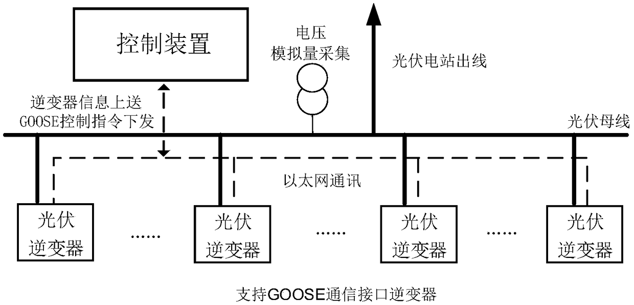
[0060] The application scenario of the present invention is a photovoltaic power station, and the schematic diagram of the control structure of the photovoltaic power station is as follows figure 1 As shown, under normal circumstances, the photovoltaic inverter outputs reactive power according to the AVC command of the upper level. The control device collects the bus voltage of the grid-connected point through PT, communicates with each photovoltaic inverter in ...


PUM


Abstract

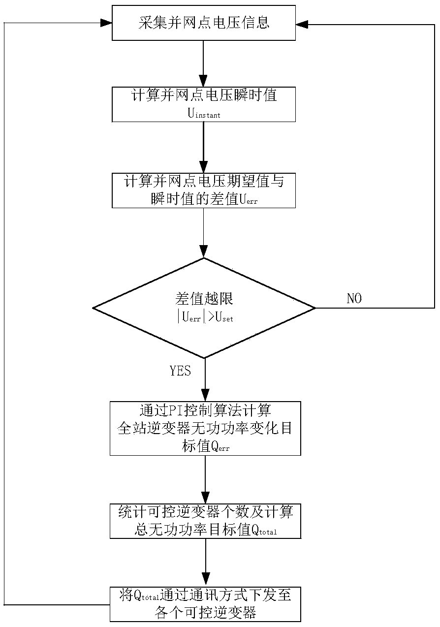
the invention discloses a method and apparatus for regulating reactive power of a photovoltaic inverter in a photovoltaic power station. The method comprises the following steps: collecting a voltageanalog signal of that photovoltaic power station, calculating the instantaneous value Uinstant of the parallel point voltage and the difference value Uerr between the instantaneous value Uinstant of the parallel point voltage and the expected value of the voltage, If | Uerr | is greater than the dead-time voltage value Uset, calculating the total station inverter reactive power change target valueQerr by a PI control algorithm according to Uerr, and calculating the number N of controllable inverters and the total reactive power target value Qtotal according to the current inverter working state, and distributing the Qtotal to each controllable inverter through communication. The invention also discloses a corresponding regulating device. The invention does not need a data window to calculate the parallel point voltage, and can quickly regulate the parallel point voltage to a preset range, so as to avoid the situation that the voltage of the photovoltaic power station exceeds the limit, and is suitable for practical engineering application.

Description

technical field [0001] The invention relates to the field of new energy generation control, in particular to the reactive power control of a photovoltaic inverter in a photovoltaic power station. Background technique [0002] Photovoltaic power generation has developed rapidly in recent years, and the proportion of photovoltaic installed capacity in some areas is already quite high. The current voltage and reactive power control system cannot meet the current grid operation adjustment requirements due to its slow response speed. , photovoltaics cannot achieve fast reactive power adjustment. In addition, in order to be able to control the bus voltage of the grid-connected point of the photovoltaic power station, the photovoltaic power station needs to be equipped with a certain capacity of SVG equipment, which occupies a large amount of investment costs of the owner in terms of equipment investment and later operation. , the above problems have seriously restricted my country's...

Claims


Application Information

Patent Timeline
IPC IPC(8): H02J3/16H02J3/50H02J3/38
CPCH02J3/383H02J3/16H02J3/50Y02E10/56Y02E40/30
Inventor 王晨王淑超侯炜陈俊段胜朋陶征王健
Owner NR ELECTRIC CO LTD
Learn More