
Mold base automatic disassembly equipment

A technology for automatic disassembly and assembly of mold bases, which is applied in metal processing equipment, metal processing, manufacturing tools, etc., and can solve the problems of inconvenient disassembly and assembly of mold bases

Active Publication Date: 2021-04-02
湖南易兴建筑有限公司
View PDF9 Cites 0 Cited by
  • Summary
  • Abstract
  • Description
  • Claims
  • Application Information

AI Technical Summary

Problems solved by technology

[0004] Based on this, it is necessary to provide an easy-to-operate automatic disassembly and assembly equipment for the traditional formwork.

Method used


Image

  • Mold base automatic disassembly equipment

Examples


Embodiment Construction

[0022] In order to facilitate the understanding of the present invention, the present invention will be described more fully below with reference to the associated drawings. Preferred embodiments of the invention are shown in the accompanying drawings. However, the present invention can be embodied in many different forms and is not limited to the embodiments described herein. On the contrary, these embodiments are provided to make the understanding of the disclosure of the present invention more thorough and comprehensive.

[0023] It should be noted that when an element is referred to as being “fixed” to another element, it can be directly on the other element or there can also be an intervening element. When an element is referred to as being "connected to" another element, it can be directly connected to the other element or intervening elements may also be present. The terms "vertical," "horizontal," "left," "right," and similar expressions are used herein for purposes ...


PUM


Abstract

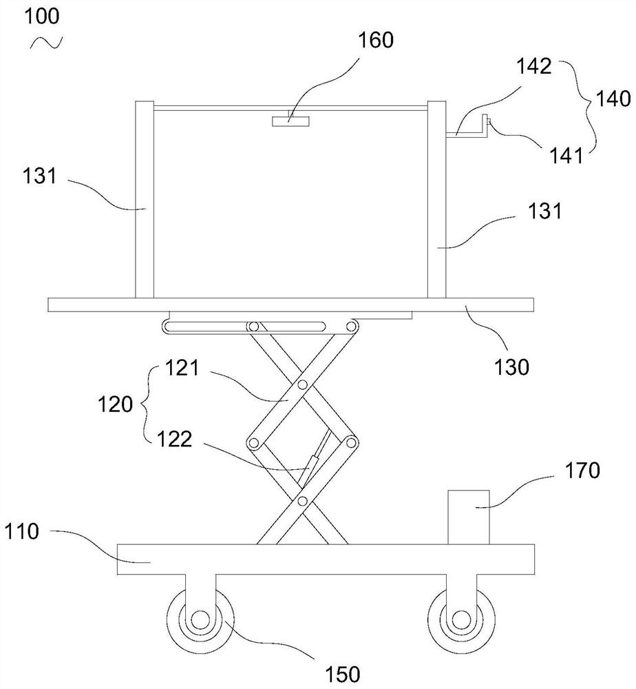
The invention relates to a formwork automatic disassembly and assembly device. The device comprises a base, a lifting assembly, a working platform, a rotating assembly and a cutting machine. One end of the lifting assembly is disposed on the surface of the base. The working platform is disposed at one end of the lifting assembly away from the base, and the lifting assembly can drive the working platform to move up and down in a direction perpendicular to the surface of the base. The rotating assembly includes a rotator. The rotator is rotatably mounted on the working platform. The rotator candrive a fixing nut to rotate forward or reversely. The cutting machine is rotatably mounted on the working platform. The cutting machine is used for cutting a fixing screw. Therefore, when a formworkneeds to be assembled or disassembled, the formwork automatic disassembly and assembly device can be moved to a designated working area to achieve vertical transportation and automatic disassembly andassembly of the formwork. The input of an operator during disassembly and assembly of the formwork is reduced, and the formwork is more convenient and quick to assemble and disassemble.

Description

technical field [0001] The invention relates to the technical field of construction engineering, in particular to an automatic disassembly and assembly device for formwork. Background technique [0002] In the field of construction engineering technology, formwork is mainly used for pouring concrete structures, etc. In the process of using the formwork, the installation and disassembly of the formwork is an essential step. At present, the installation and disassembly of the formwork are all realized by manual work. [0003] However, since the installation space of the formwork is usually relatively small and the installation environment is relatively complicated at the construction site, a large amount of manpower is required to manually disassemble the formwork, which makes the disassembly and assembly of the formwork very inconvenient. Contents of the invention [0004] Based on this, it is necessary to provide an easy-to-operate automatic disassembly and assembly equi...

Claims


Application Information

Patent Timeline
Patent Type & Authority Patents(China)
IPC IPC(8): B23P19/06
CPCB25B27/14B25H1/04B25H1/16
Inventor 尹芬芳
Owner 湖南易兴建筑有限公司
Learn More