An electrical control switch structure

A technology of electrical control and switch structure, applied in the direction of electrical switches, circuits, electrical components, etc., can solve the problems of lack of overall unity and relative stability, difficult for users to recover, and appearances that are not related to each other.

Inactive Publication Date: 2015-08-19
SUZHOU AOPEIKE AUTOMOBILE ELECTRONICS
View PDF5 Cites 0 Cited by
  • Summary
  • Abstract
  • Description
  • Claims
  • Application Information

AI Technical Summary

Problems solved by technology

[0006] The first combination is just to install two independent electrical control switches as close as possible to each other, and the two are not related to each other in appearance. Because this way is independent of each other, it lacks overall unity and relative stability
[0007] The second combination (such as figure 2 As shown in ), it adopts independent groove assembly, and the assembly section is "T" shape. It is assembled by the convex fitting B on the side of the electrical control switch and the concave fitting C on the side of another electrical control switch. Compared with The first is an obvious improvement, but the fly in the ointment is that the independent narrow slideway can not solve the relative stability problem between the two electrical control switches.
[0008] Therefore, it is difficult to avoid the problem that the user installs and travels to correct the current existing technology of the electrical control switch through the wire slot and its installation structure:
[0009] The disadvantage of breaking off is that if the user breaks in the wrong direction, it is more difficult to recover
May leave a gap, which is not very good looking
Compared with the snap-off type, the advantage of the plug-in type is that it can be restored when it is misoperated, but after the installation is found to be in the wrong position, the user has to disassemble it and reinstall it, which is relatively cumbersome.
[0010] Moreover, the current switch expansion module combination structure: cannot well solve the problem of close integration and relative stability between the main body and the expansion unit

Method used


Image

  • An electrical control switch structure
  • An electrical control switch structure
  • An electrical control switch structure

Examples


Embodiment Construction

[0027] In order to have a further understanding and understanding of the structural features of the present invention and the achieved effects, the preferred embodiments and accompanying drawings are used for a detailed description, as follows:

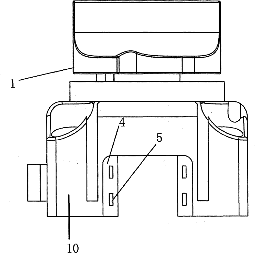
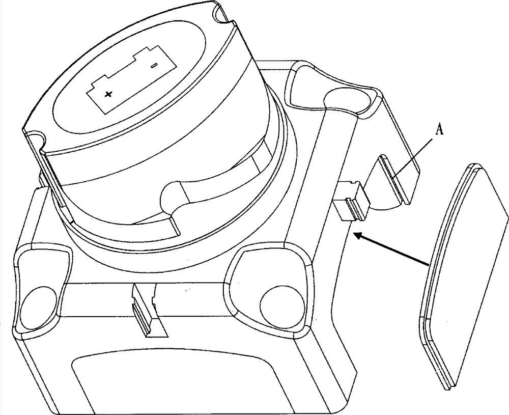
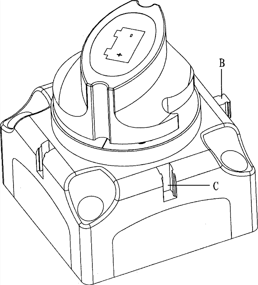
[0028] In order to better manage the wires inside the electrical control switch, a movable switch door needs to be set on one side of the electrical control switch, and image 3 , Figure 4 It is the installation structure diagram of the wire slot of the electrical control switch of the present invention, as shown in the figure. The structure of the electrical control switch mainly adopts a "press buckle" wire slot structure, including an electrical control switch 1 and a cover plate 2 installed on the first side 10 of the electrical control switch 1, and the cover plate 2 is provided with a bayonet The column 3 and the first side 10 of the electrical control switch 1 are provided with a bayonet surface 4 , the bayonet surface 4 is p...


PUM


Abstract

The invention relates to an electrical appliance control switch structure, comprising an electrical appliance control switch and a cover plate which is arranged on a first side face of the electrical appliance control switch, wherein the cover plate is provided with a bayonet post; the first side face of the electrical appliance control switch is provided with a bayonet face; the bayonet face is provided with a bayonet groove; the bayonet groove is matched and connected with the bayonet post; grooves are arranged at the left and right sides of the first side face of the electrical appliance control switch respectively; and a second side face of the electrical appliance control switch is provided with a bolt which is matched and connected with the groove. A pressing buckle type switch and a threading groove structure are used to solve the defects in the prior art, thus avoiding unrecoverable misoperation and solving the unreasonable post-installation adjustment in a certain range. The composite structure of electrical appliance control switch expansion modules is used to solve the problem that the structure between the body and an expansion unit is incompact and unstable.

Description

technical field [0001] The invention relates to an electric appliance control switch structure in the field of automobile and marine control, in particular to an electric appliance control switch structure with a "press buckle" wire slot structure and an extended module combination structure. Background technique [0002] At present, there are two common electrical control switch wire slots and their installation structures: [0003] The first one is the break-off method: the disadvantage of this method is that if the user breaks in the wrong direction, it will be more difficult to recover, and a gap may be left, which will lead to a bad appearance. [0004] The second (such as figure 1 (shown) is the plug-in type, that is, the cover is directly inserted and installed through the two slots A on the side of the electrical control switch. If the mouth is wrong, the user has to dismantle it and reinstall it, which is relatively cumbersome. [0005] At present, there are two ...

Claims


Application Information

Patent Timeline
Patent Type & Authority Patents(China)
IPC IPC(8): H01H9/02
Inventor 潘志梅陈威
Owner SUZHOU AOPEIKE AUTOMOBILE ELECTRONICS
Why Eureka
Try Eureka