Polyurethane foaming machine

A technology of polyurethane and foaming machine, applied in the field of polyurethane foaming machine, can solve the problems of unstable polyurethane foaming process, poor molding precision of polyurethane foaming material, difficulty in producing high-quality finished products, etc., so as to improve the stirring effect and improve the Mixing effects, effects that improve usability

Active Publication Date: 2019-01-25
郑州孚莱孚特性材料有限公司
View PDF10 Cites 9 Cited by
  • Summary
  • Abstract
  • Description
  • Claims
  • Application Information

AI Technical Summary

Problems solved by technology

The quality of polyurethane products is directly related to the mixing uniformity of polyurethane material A and material B. At the same time, when mixing polyurethane raw materials, it is necessary to ensure that a sufficient amount of gas is mixed into the raw materials and the gas is evenly distributed in the polyurethane raw materials; but the traditional The polyurethane foaming machine uses a metering pump to drive polyurethane material A and material B into the mixing head at a set ratio and flow rate. When the one-way valve of the mixing head is opened, material A and material B are mixed in the mixing head, and the compressed gas blows out the mixed material. The head is injected into the mold to produce the finished product, which makes the polyurethane foaming process extremely unstable, resulting in poor molding accuracy of the produced polyurethane foam material, and it is difficult to produce high-quality finished products

Method used


Image

  • Polyurethane foaming machine
  • Polyurethane foaming machine
  • Polyurethane foaming machine

Examples


Embodiment Construction

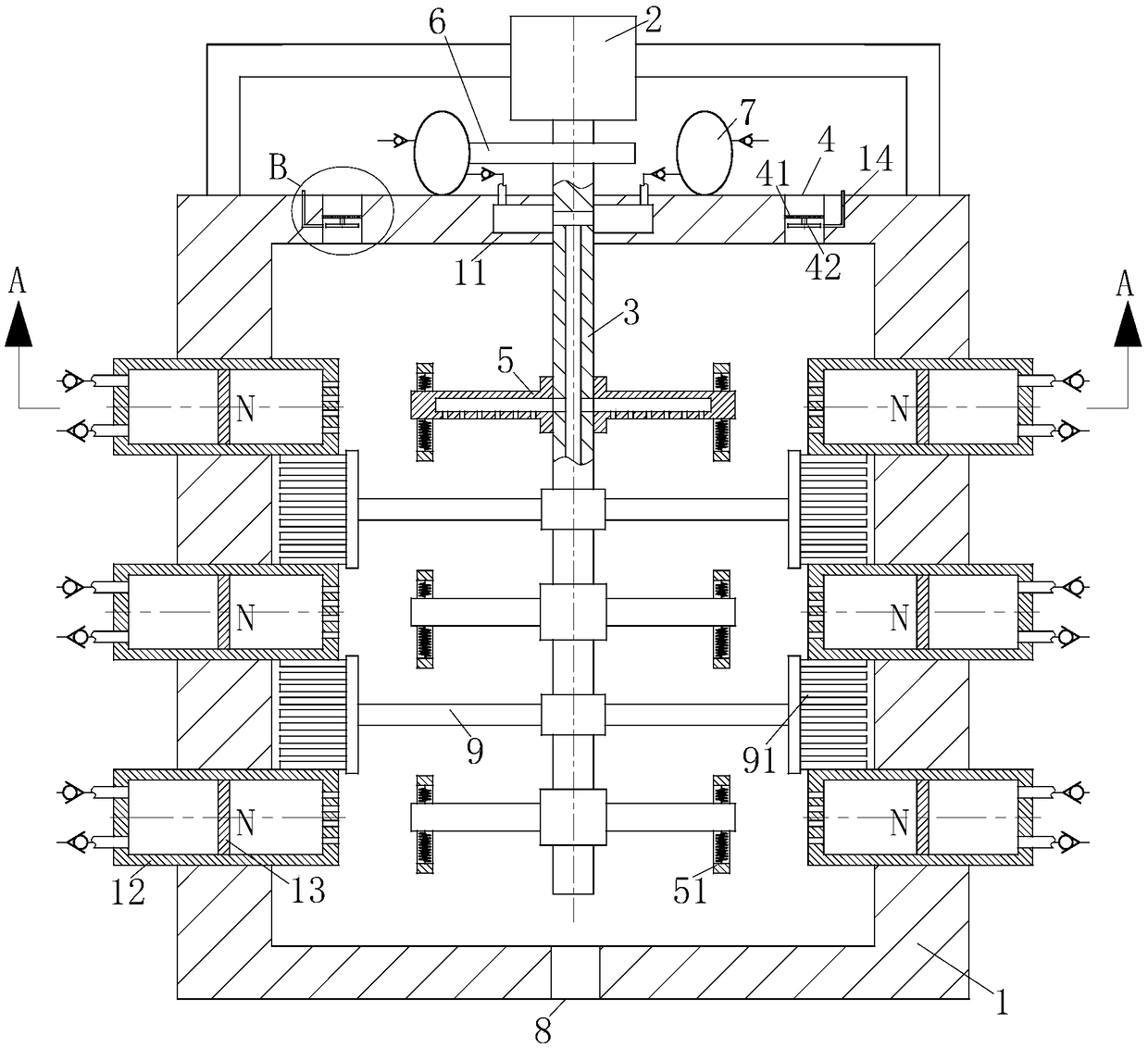
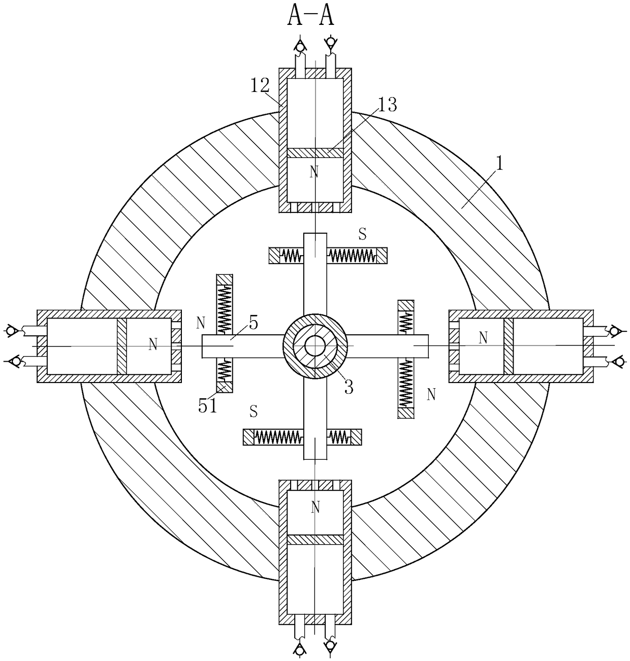
[0018] use Figure 1-Figure 3 The structure of the polyurethane foam machine which concerns on one Embodiment of this invention is demonstrated below.

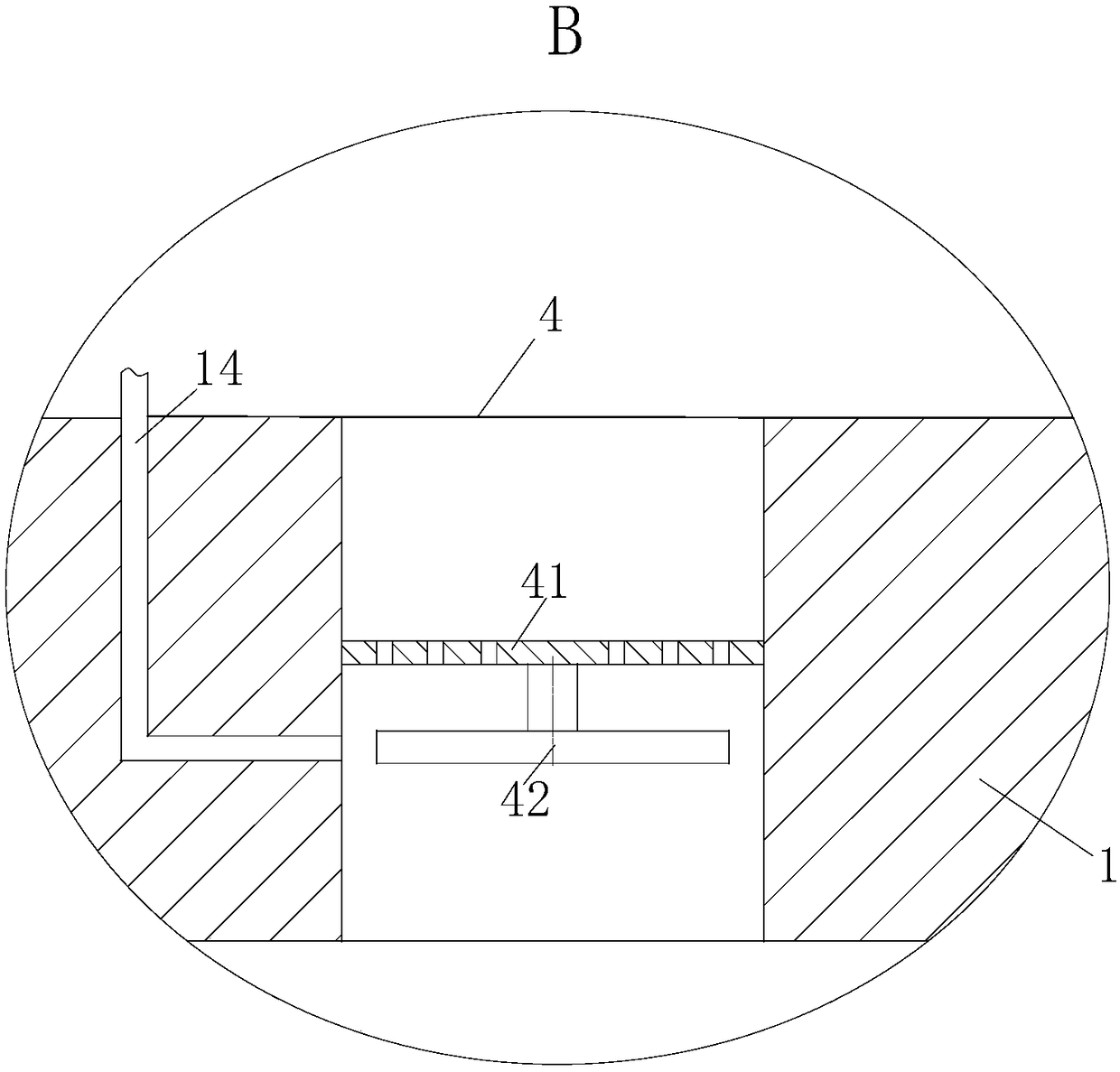
[0019] Such as figure 1As shown, a polyurethane foaming machine according to the present invention includes a housing 1, a motor 2, a connecting shaft 3, a feed inlet 4, a No. 1 stirring rod 5, a cam 6, an air bag 7 and a discharge outlet 8; The motor 2 is installed on the top of the housing 1; the connecting shaft 3 is installed inside the housing 1 through the output shaft of the motor 2, and a channel is provided inside the connecting shaft 3; the number of the feeding ports 4 is two, and the feeding ports 4 are about It is symmetrically arranged on the top of the housing 1, and the feeding port 4 is used to inject polyurethane A material and B material into the housing 1 respectively; multiple groups of No. 1 stirring rods 5 are fixedly installed on the connecting shaft 3, and each group of The number of No. 1 stirring r...


PUM


Abstract

The invention belongs to the technical field of polyurethane production equipment, and in particular relates to a polyurethane foaming machine. The polyurethane foaming machine comprises a shell, a motor, a connecting shaft, feeding holes, stirring rods No. 1, a cam, an air bag and a discharge hole, wherein the motor is installed on the top of the shell; the connecting shaft is installed in the shell by means of a motor output shaft; a channel is arranged in the connecting shaft; the two feeding holes are available and are respectively formed at the left and right of the top of the shell in asymmetrical way; the plurality of groups of stirring rods No. 1 are fixedly installed on the connecting shaft, and an even number of stirring rods No. 1 are available in each group; each stirring rodNo. 1 is internally provided with a channel, and the channels in the stirring rods No. 1 are communicated with the channel in the connecting shaft; the lower surfaces of the stirring rods No. 1 are provided with pores; the cam is installed on the motor output shaft; a circular cavity is arranged on the top of the shell, and is communicated with the interior of the connecting shaft; the air bag isfixed on the top of the shell; the discharge hole is formed in the bottom of the shell.

Description

technical field [0001] The invention belongs to the technical field of polyurethane production equipment, in particular to a polyurethane foaming machine. Background technique [0002] At present, with the continuous improvement of people's living standards, polyurethane foam materials are widely used in many fields such as production and life, such as polyurethane insulation materials, polyurethane shutter doors and windows, polyurethane tiles, polyurethane composite glass, polyurethane furniture, polyurethane flower pots and polyurethane guardrail etc. The quality of polyurethane products is directly related to the mixing uniformity of polyurethane material A and material B. At the same time, when mixing polyurethane raw materials, it is necessary to ensure that a sufficient amount of gas is mixed into the raw materials and the gas is evenly distributed in the polyurethane raw materials; but the traditional The polyurethane foaming machine uses a metering pump to drive po...

Claims


Application Information

Patent Timeline
Patent Type & Authority Applications(China)
IPC IPC(8): B29C44/04B29C44/34B29K75/00
CPCB29C44/04B29C44/34B29C44/3442B29K2075/00
Inventor 林枫
Owner 郑州孚莱孚特性材料有限公司
Why Eureka
Try Eureka