
Speed regulation control system, aerial work platform and speed regulation method

A high-altitude work platform and control system technology, which is applied in the direction of lifting devices, can solve the problems of high-altitude work platform safety and hidden dangers, and achieve the effect of reducing safety hazards and improving safety factor

Pending Publication Date: 2019-01-25
SANY PALFINGER SPECIAL VEHICLE
View PDF11 Cites 3 Cited by
  • Summary
  • Abstract
  • Description
  • Claims
  • Application Information

AI Technical Summary

Problems solved by technology

[0004] The operation of aerial work platforms has a large safety hazard

Method used


Image

  • Speed regulation control system, aerial work platform and speed regulation method
  • Speed regulation control system, aerial work platform and speed regulation method
  • Speed regulation control system, aerial work platform and speed regulation method

Examples


Embodiment 1

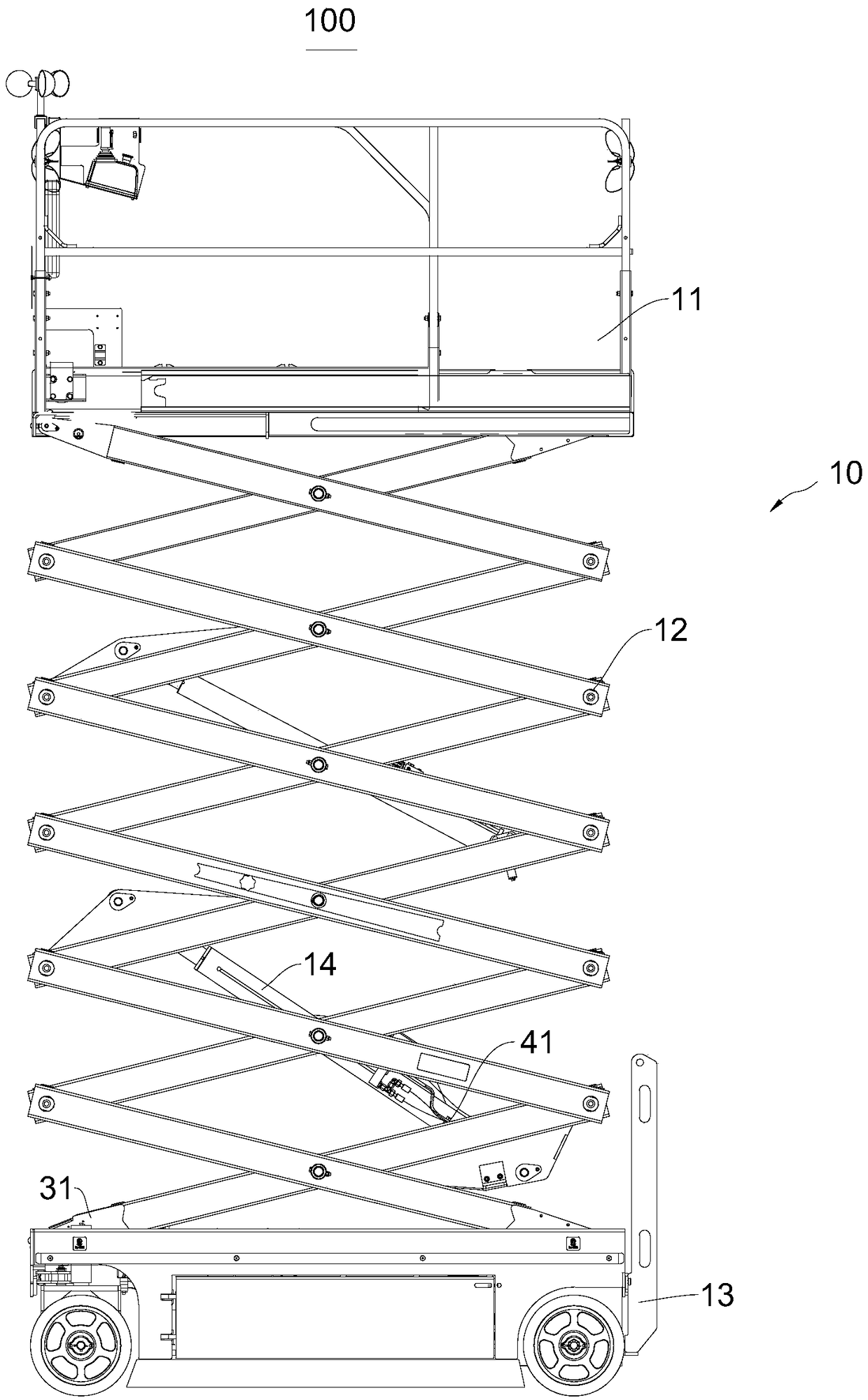
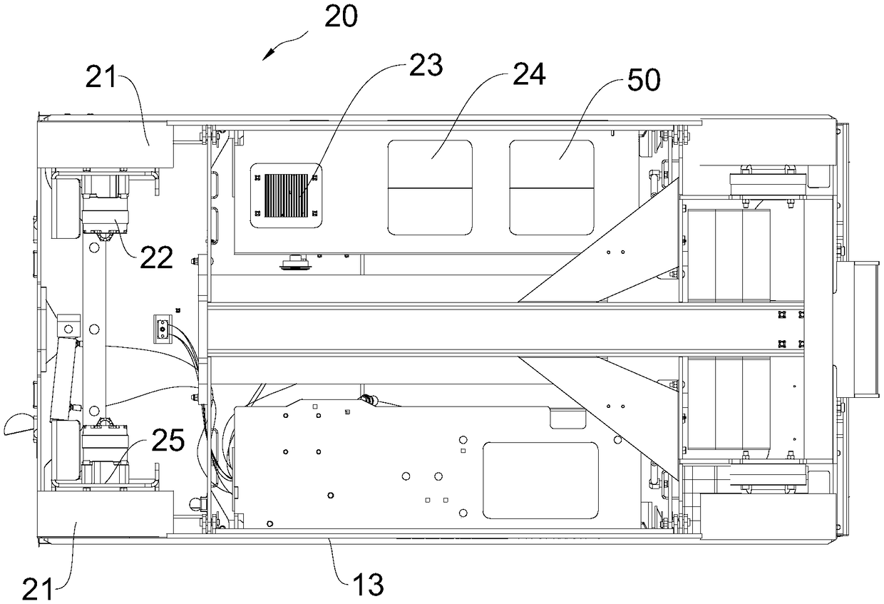
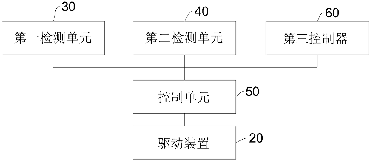
[0045] Please refer to Figure 1-Figure 6 , this embodiment provides an aerial work platform 100, and correspondingly, a speed regulation control system is provided.

[0046] The aerial work platform 100 includes the speed control system, which has all the functions of the speed control system.

[0047] Specifically, combine figure 1 and figure 2, the aerial work platform 100 includes a body 10 and a driving device 20, the driving device 20 is used to drive the body 10 to move, more specifically, the body 10 is a scissor type aerial work platform, which includes a working part 11, a driving cylinder 14, a folding frame 12 and the chassis 13, the working part 11, the folding frame 12 and the chassis 13 are connected in sequence, and the drive cylinder 14 is used to drive the folding frame 12. During work, the chassis 13 is placed on the ground, and the driving device 20 is connected to the chassis 13 for driving the chassis 13 to move. The driving cylinder 14 drives the fol...

Embodiment 2

[0081] This embodiment provides a speed regulation method, which is realized by using the above-mentioned speed regulation control system or the above-mentioned aerial work platform 100. The speed regulation method includes:

[0082] Outputting a first signal representing the height of the working part 11;

[0083] Outputting a second signal representing the load of the working part 11;

[0084] Receive the first signal and the second signal and perform arithmetic processing, and control the driving device 20 .

[0085] In summary, the present invention provides a speed regulation control system, through the first signal detected by the first detection unit 30 and the second signal detected by the second detection unit 40, the control unit 50 can Calculate and process with the second signal to obtain the maximum traveling speed of the aerial work platform 100, and control the driving device 20 to realize the control of the traveling speed of the aerial work platform 100, so t...


PUM


Abstract

The embodiment of the invention provides a speed regulation control system, an aerial work platform and a speed regulation method, and relates to the technical field of the aerial work. The speed regulation control system is used for the aerial work platform, and the aerial work platform comprises a body and a driving device. The driving device is used for driving the body to move. The body comprises a working part, and the speed regulation control system comprises a first detection unit, a second detection unit and a control unit communicating with both the first detection unit and the seconddetection unit; the first detection unit is used for outputting a first signal representing the height of the working part; the second detection unit is used for outputting a second signal representing the load of the working part; the control unit is used for receiving the first signal and the second signal, performing arithmetic processing and controlling the driving device. According to the speed regulation control system, the maximum running speed of the aerial work platform can be limited, so that the aerial work platform can freely run in a safe speed, potential safety hazards can be reduced, and safety factors of operators and the aerial work platform can be improved.

Description

technical field [0001] The invention relates to the technical field of high-altitude operations, in particular to a speed regulation control system, a high-altitude operation platform and a speed regulation method. Background technique [0002] Aerial work platforms are generally operated outdoors. At present, the driving speed of aerial work platforms on the market is controlled by an independent system. The driving speed of aerial work platforms can only be controlled according to the operator's wishes or experience. Operating an aerial work platform can pose significant safety hazards. [0003] The inventor found in the research that there are at least the following shortcomings in the existing related technologies: [0004] The operation of aerial work platforms has great potential safety hazards. Contents of the invention [0005] The purpose of the present invention includes, for example, to provide a speed regulation control system, which can improve the deficienc...

Claims


Application Information

Patent Timeline
Patent Type & Authority Applications(China)
IPC IPC(8): B66F11/04
CPCB66F11/042
Inventor 刘丹陆进添谢仁军
Owner SANY PALFINGER SPECIAL VEHICLE
Learn More