Overflow system

An overflow and overflow groove technology, used in safety valves, engine components, balance valves, etc., can solve the problems of left and right swaying of the valve core, low valve core service life, excessive deformation of the sealing ring, etc., and achieve convenient overflow function. , long service life, uniform force effect

Pending Publication Date: 2019-01-25
NINGBO HUAXUN CLEANING MACHINERY
View PDF0 Cites 0 Cited by
  • Summary
  • Abstract
  • Description
  • Claims
  • Application Information

AI Technical Summary

Problems solved by technology

[0003] 1. Because the valve core is not always in contact with the sealing ring, when the valve core moves and squeezes the sealing ring under pressure, it is easy to deform the sealing ring too much, which makes the service life of the sealing ring lower;
[0004] 2. Because the valve core is not always in contact with the sealing ring, it is equivalent to the fact that only the lower part of the valve stem and the valve core is supported by a support point, while

Method used


Image

  • Overflow system
  • Overflow system

Examples


Example Embodiment

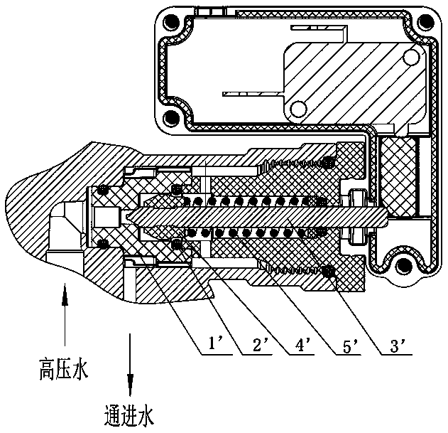
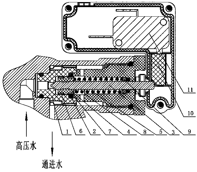
[0018] Specific embodiment one, an overflow system, including a valve seat 1, a sealing ring embedded in the valve seat 1, a valve stem 3 arranged in the valve seat 1, a valve core 4 sleeved on the valve stem 3, and The spring 5 used to resist the valve core 4, of which:

[0019] The valve core 4 is cylindrical, and the outer circumference of the valve core 4 is in interference fit with the sealing ring, and when the valve core 4 moves back and forth in the valve seat 1, the valve core 4 is always matched with the sealing ring 2; and The core 4 is divided into three parts along the direction of the valve stem, from top to bottom, the first part, the second part and the third part. The outer circumference of the first part is provided with an upper overflow groove 6, and the third part is provided with an outer circumference The specific thickness of the three parts of the underflow groove 7 is determined according to actual conditions, but in this specific embodiment, the thickne...

Example Embodiment

[0023] The second embodiment differs from the first embodiment in that the valve core 4 in the second embodiment is cylindrical.

Example Embodiment

[0024] The third embodiment differs from the first embodiment in that, in the third embodiment, a limit step 8 is also provided in the valve seat, so that when the valve core 4 moves, it will be blocked by the limit step 8.


PUM


Abstract

The invention relates to the technical field of high-pressure cleaning machine, in particular to an overflow system. The overflow system comprises a valve seat (1), a sealing ring (2) embedded in thevalve seat (1), a valve rod (3) arranged in the valve seat (1), a valve core (4) arranged on the valve rod (3) in a sleeving manner, and a spring (5) for resisting the valve core (4). The outer circumference of the valve core (4) is in interference fit with the sealing ring (2), and the valve core (4) is divided into three parts along a valve rod direction: a first part, a second part and a thirdpart in sequence from top to bottom; an upper overflow slot (6) is formed in the outer circumference of the first part; and a lower overflow slot (7) is formed in the outer circumference of the thirdpart. The overflow system is relatively long in service life and relatively low in noise.

Description

technical field [0001] The invention relates to the technical field of high-pressure cleaning machines, in particular to an overflow system. Background technique [0002] The overflow system is an important part of the pressure washer. Prior art overflow systems such as figure 1 As shown, it mainly includes a valve seat 1', a sealing ring 2' embedded in the valve seat, a valve stem 3' set in the valve seat, a valve core 4' sleeved on the valve stem, and a The spring 5' of the core, because the valve core of the prior art adopts a shuttle-like structure, it is not always in contact with the sealing ring, and in order to overflow, it is necessary to reserve a certain overflow between the valve core and the valve seat. flow gap, which leads to the following disadvantages: [0003] 1. Because the valve core is not always in contact with the sealing ring, when the valve core moves and squeezes the sealing ring under pressure, it is easy to deform the sealing ring too much, whi...

Claims


Application Information

Patent Timeline
IPC IPC(8): F16K17/04
CPCF16K17/04
Inventor 朱蔚
Owner NINGBO HUAXUN CLEANING MACHINERY
Why Eureka
Try Eureka