Waterproof LED lamp

A technology for LED lamps and lampshades, which is applied to gas/waterproof devices, lighting devices, light sources, etc., can solve the problems of lack of sealing function and poor waterproof effect, achieve good waterproof effect, improve service life, and avoid the effect of shaking from side to side

Active Publication Date: 2019-01-25
宁波智正伟盈信息科技有限公司
View PDF8 Cites 2 Cited by
  • Summary
  • Abstract
  • Description
  • Claims
  • Application Information

AI Technical Summary

Problems solved by technology

[0005] Aiming at the deficiencies of the prior art, the present invention provides a waterproof LED lamp, which has the advantages of being able to seal the gap between the LED lamp and the lamp cover, and has a good waterproof effect, and solves the problem of most of the existing LED lamp cover. It is fixed by simple thread or clamping, lack of sealing function, and poor waterproof effect

Method used


Image

  • Waterproof LED lamp
  • Waterproof LED lamp
  • Waterproof LED lamp

Examples


Embodiment 2

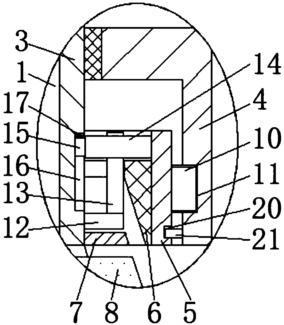
[0034]Embodiment 2: The difference from Embodiment 1 is that the surface of the fixed cylinder 5 is fixedly connected with the limit ring 10, the inner wall of the transmission cylinder 4 is provided with a limit groove 11, and the limit ring 10 is slidably connected in the inside of the limit groove 11. By setting The limit ring 10 and the limit groove 11 can support the fixed cylinder 5 at the same time, avoiding the left and right shaking of the fixed cylinder 5, and improving the stability of the fixed cylinder 5 when it moves.

Embodiment 3

[0035] Embodiment 3: The difference from Embodiment 1 is that both sides of the threaded sleeve 3 are fixedly connected with a backing plate 12 at the top of the fixed sleeve 7, and the top of the backing plate 12 is fixedly connected with a limit rod 13 on the side away from the threaded sleeve 3. The tops on both sides of the inner wall of the fixed cylinder 5 are fixedly connected to the limit plate 14, and the top of the limit rod 13 penetrates to the top of the limit plate 14. By setting the limit plate 14 and the limit rod 13, the fixed cylinder 5 can be limited. Position, to avoid the rotation of the fixed cylinder 5 when moving up and down, so that the oblique sealing ring 6 and the fixed sleeve 2 8 produce friction, resulting in the phenomenon that the lampshade 2 rotates and falls.

Embodiment 4

[0036] Embodiment 4: The difference from Embodiment 1 is that the side of the limiting plate 14 close to the threaded sleeve 3 is fixedly connected with a slider 15, and both sides of the threaded sleeve 3 are provided with chute 16, and the slider 15 is slidably connected to the chute 16, the top of the inner wall of the chute 16 is fixedly connected with a rubber pad 17, and the bottom of the rubber pad 17 is in contact with the top of the slider 15. By setting the slider 15 and the chute 16, the limit plate 14 can be limited. The support strength of the limit rod 13 to the limit plate 14 is improved, the phenomenon of the limit plate 14 shaking left and right is avoided, and the service life of the limit rod 13 is improved.


PUM


Abstract

The invention discloses a waterproof LED lamp. The waterproof LED lamp comprises an LED lamp body, wherein a lampshade is arranged on the bottom of the LED lamp body; the top of the lampshade is in threaded connection to the inside of the LED lamp body; the surface of the lampshade is fixedly connected with a light dimming mechanism; and the bottom of the surface of the LED lamp body is fixedly connected with a threaded sleeve. A transmission barrel drives a fixing barrel to move downwards through a limiting groove and a limiting ring, the fixing barrel drives an oblique sealing ring to downwards extrude a first fixing sleeve and a second fixing sleeve, thus, the first fixing sleeve and the second fixing sleeve are inlaid in the oblique sealing ring to a certain degree, and therefore, thewaterproof LED lamp has the advantages that a seam between the LED lamp and a lamp case is sealed and a waterproof effect is good. The problems that lamp cases of most of existing LED lamps are fixedby a simple threaded or clamped connection mode, a sealing function is not fulfilled, and a waterproof effect is poor are solved, and meanwhile, short-circuiting of the LED lamp due to the fact that water easily permeates into the lamp from seams is avoided.

Description

technical field [0001] The invention relates to the technical field of LED lamps, in particular to a waterproof LED lamp. Background technique [0002] LED light is an electroluminescent semiconductor material chip, which is solidified on the bracket with silver glue or white glue, and then connected to the chip and circuit board with silver or gold wires. As a representative of green lighting, LED lights are characterized by energy saving. It is becoming more and more popular. [0003] With the improvement of people's living standards, various LED lamps are widely used in the field of lighting, and some LED lamps are specially designed for outdoor lighting. It is fixed directly, lacks the sealing function, and the waterproof effect is poor. Water easily seeps into the inside of the lamp from the gap and causes a short circuit in the LED lamp, which is not convenient for people to use. Contents of the invention [0004] (1) Solved technical problems [0005] Aiming at t...

Claims


Application Information

Patent Timeline
Patent Type & Authority Applications(China)
IPC IPC(8): F21K9/20F21V17/12F21V31/00F21Y115/10
CPCF21V17/12F21V31/005F21K9/20F21Y2115/10
Inventor 曾美霞
Owner 宁波智正伟盈信息科技有限公司
Why Eureka
Try Eureka