

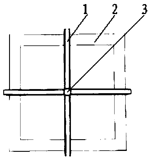
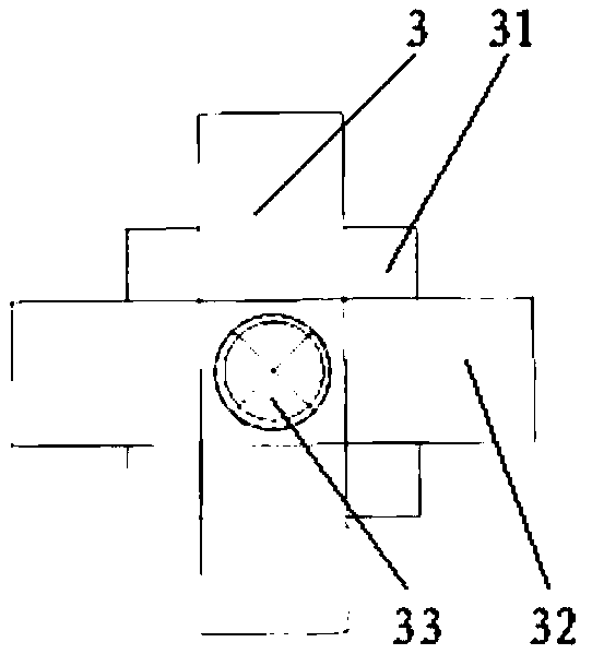
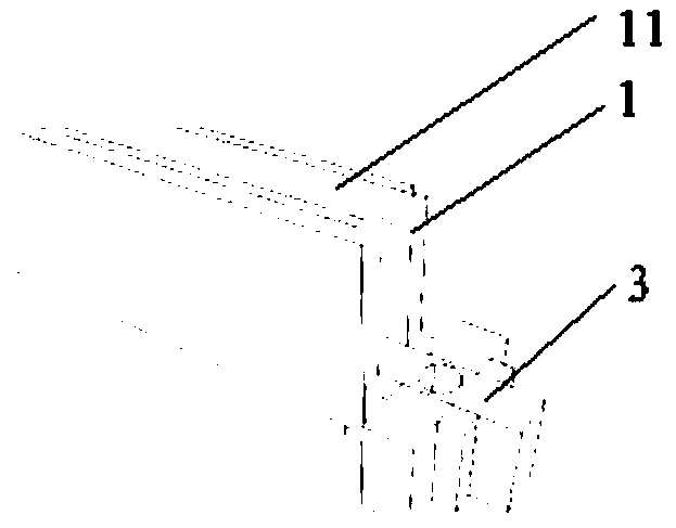
Dual-use target image control point for UAV photogrammetry and radar scanning
A technology of photogrammetry and radar scanning, which is applied in photogrammetry/video metrology, measuring scales, measuring point marks, etc., can solve the problem of large data processing volume, achieve easy unification of coordinate data, reduce field workload, The effect of reducing workload
- Summary
- Abstract
- Description
- Claims
- Application Information
AI Technical Summary
Problems solved by technology
Method used
Image

Examples
Embodiment Construction
[0025] The following will clearly and completely describe the technical solutions in the embodiments of the present invention with reference to the accompanying drawings in the embodiments of the present invention. Obviously, the described embodiments are only some, not all, embodiments of the present invention. Based on the embodiments of the present invention, all other embodiments obtained by persons of ordinary skill in the art without making creative efforts belong to the protection scope of the present invention.
[0026] The purpose of the present invention is to provide a dual-purpose target image control point for unmanned aerial vehicle photogrammetry and radar scanning, to solve the problems in the above-mentioned prior art, so that the present invention can be used as a dual-purpose target image for photography and radar scanning control points, which reduces the workload of image control point layout and the processing of measurement data.
[0027] In order to mak...
PUM
 Abstract
Description
Claims
Application Information