Detachable vertical type soap box

A soap dish and detachable technology, which is applied in the field of detachable vertical soap dish, can solve the problems of slippage and occupy a lot of space, and achieve the effect of prolonging the use time.

Active Publication Date: 2019-01-29
SHANGHAI OCEAN UNIV
View PDF9 Cites 2 Cited by
  • Summary
  • Abstract
  • Description
  • Claims
  • Application Information

AI Technical Summary

Problems solved by technology

[0003] However, the existing soap boxes still have certain defects when they are used. Most of the existing soap boxes are horizontal soap boxes, which take up a lot of space and have problems such as slippage due to the soap being wet in the process of using soap.

Method used


Image

  • Detachable vertical type soap box
  • Detachable vertical type soap box
  • Detachable vertical type soap box

Examples


Embodiment 1

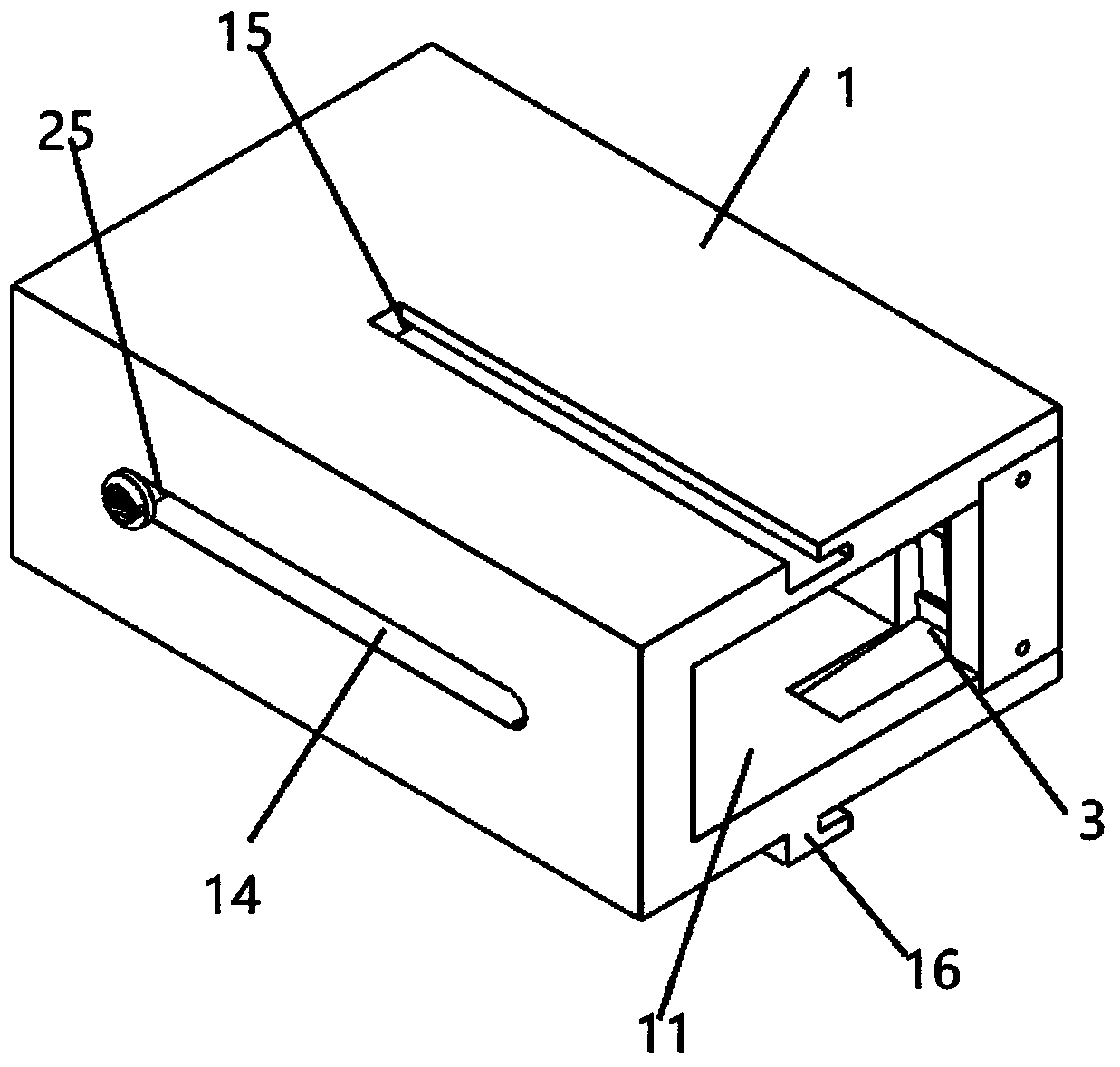
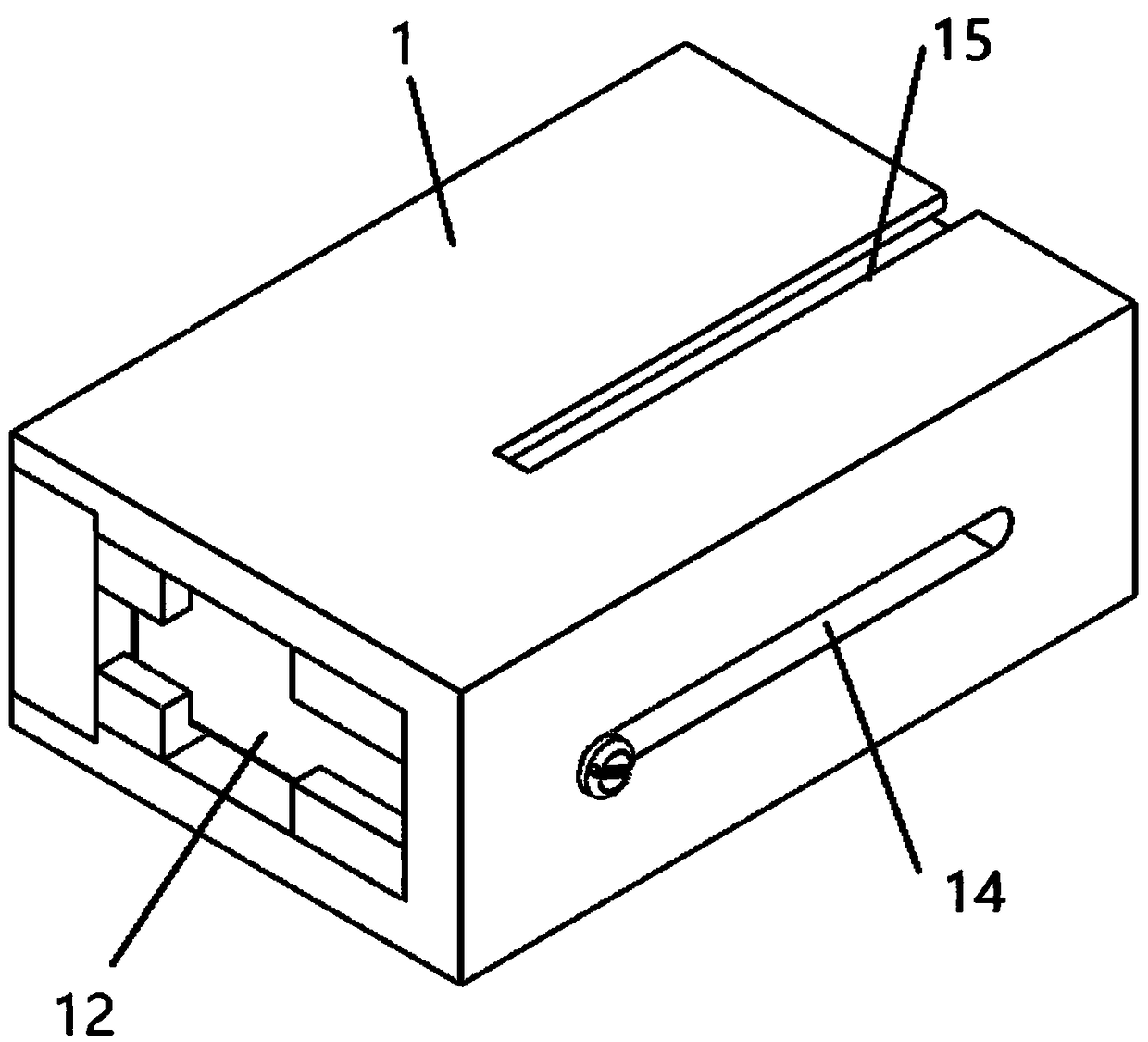
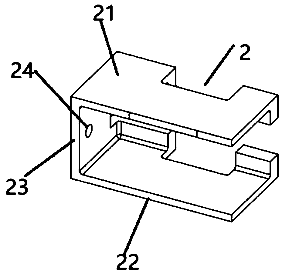
[0027] Such as Figure 1-8 As shown, a detachable vertical soap box proposed by the present invention includes a soap shell 1 in a cuboid structure, and also includes a soap holder 2 and a clamping mechanism 3;

[0028] There is a cavity in the middle of the soap shell 1, a rectangular-shaped feeding port 11 is opened at one end of the soap shell 1, and a "ten"-shaped through hole 12 is opened at the other end of the soap shell 1, and the inner wall of the side wall of the soap shell 1 A slot 13 in a rectangular parallelepiped structure is vertically opened on the side close to the discharge port 11, a chute 14 in a bar-shaped structure is opened horizontally on the other side wall of the soap shell 1, and a rectangular parallelepiped structure is opened horizontally on the side wall of the soap shell 1 The through groove, and the position of the through groove corresponds to the central position of the slot 13, and the feed port 11 is used to feed the soap into the soap shell...

Embodiment 2

[0032] Please continue to refer Figure 1-8 Different from the above-mentioned embodiments, further, the middle part of the upper end surface of the soap case 1 is concavely provided with an "L"-shaped installation groove 15, and the middle part of the lower end surface of the soap case 1 is convexly provided with an "L"-shaped buckle 16, And the specification of buckle 16 is compatible with the specification of installation groove 15.

[0033] By adopting the above technical solution, the mounting groove 15 on one soap box can be used to engage and fix the buckle 16 on the other soap box, so that the two soap boxes can be locked and fixed to each other, which is convenient for placing multiple pieces of soap.

[0034] Further, one end of the bolt 24 protruding from the soap case 1 is threadedly connected to the push handle 25, the push handle 25 has a circular structure, and the outer side wall of the push handle 25 is convexly provided with a number of parallel wave stripes,...


PUM


Abstract

The invention discloses a detachable vertical type soap box, and relates to the technical field of soap box application. The detachable vertical type soap box comprises a soap shell of a cuboid structure, a soap holder and a clamping mechanism. The detachable vertical type soap box has the beneficial effect that by arranging the clamping mechanism, a user can clamp and fix a soap in a buckled modethrough two clamping jaws symmetrically arranged on the clamping mechanism, and therefore the problem that the soap surface is wet and not prone to being fixed when the soap is used is solved. The soap box can be placed vertically, liquid adhered to the soap can be conveniently drained by a cross-shaped through hole formed in the soap box so that the soap can be dried quickly, the soap is prevented from turning rotten due to soaking in water for a long time, and the service time of the soap is effectively prolonged. A mounting groove and a clamping buckle which are matched with each other areseparately arranged on the upper and lower end faces of the soap shell, the mounting groove in one soap shell is used for being clamped and fixed to the clamping buckle on the other soap shell in a buckled mode, so that the two soap shells can be buckled and fixed with each other, multiple soap shells can be spliced mutually, and multiple soaps can be fixed at one time.

Description

technical field [0001] The invention relates to the technical field of soap box application, in particular to a detachable vertical soap box. Background technique [0002] A container for soap, soap. Generally placed in toilets, washrooms and other places. The advantage is that it is easy to use, it can effectively protect the soap from being dissolved by water, and its color is fresh and bright, which can also bring people a good mood. The shape of the soap box is also changeable and distinctive, which can meet the needs of different bathrooms. [0003] However, existing soap boxes still have certain defects when they are in use. Most of the existing soap boxes are horizontal soap boxes, which take up a lot of space and have problems such as slippage due to the soap being stained with water in the process of using soap. Therefore we are necessary to improve existing soap box, to overcome above-mentioned defective. Contents of the invention [0004] The object of the pr...

Claims


Application Information

Patent Timeline
Patent Type & Authority Applications(China)
IPC IPC(8): A47K5/02A47K5/05
CPCA47K5/02A47K5/05Y02W30/80
Inventor 陈欣怡李亚美龙振东张项羽陈瀚铮夏志露田卡王世明刘晨
Owner SHANGHAI OCEAN UNIV
Why Eureka
Try Eureka