
Head-neck flank damping structure, safety headrest and child safety seat

A shock-absorbing mechanism and side wing technology, which is applied to child seats, vehicle seats, special positions of vehicles, etc., can solve problems such as secondary injuries, no side impact protection devices, and children's injuries, and achieve the effect of reducing impact force

Pending Publication Date: 2019-01-29
BUTONG SAFETY TECH (NINGBO) CO LTD
View PDF1 Cites 1 Cited by
  • Summary
  • Abstract
  • Description
  • Claims
  • Application Information

AI Technical Summary

Problems solved by technology

Many existing car accidents are caused by side impacts, and most of the child safety seats on the market do not have side impact protection devices. When a side impact occurs, the child seated is often not well protected.
There are also some producers who have produced child safety seats with side protection, such as the patent: The side protection structure (publication number: CN204749903U) of a child safety seat for cars comprises a side wing foam board, a reverse side collision frame and an anti-side collision foam board, but the reverse side The impact frame is in the shape of a straight plate, and the anti-side impact foam board is fixed on the anti-side impact frame. In an actual collision, only relying on the material of the anti-side impact foam board itself cannot fully buffer the impact of the side impact, and it will still be on the safety seat. The child in the chair is injured, and because the straight plate shape of the anti-side collision frame directly transmits the impact force of the collision, the child may collide back and forth between the frames on both sides, causing secondary injury

Method used


Image

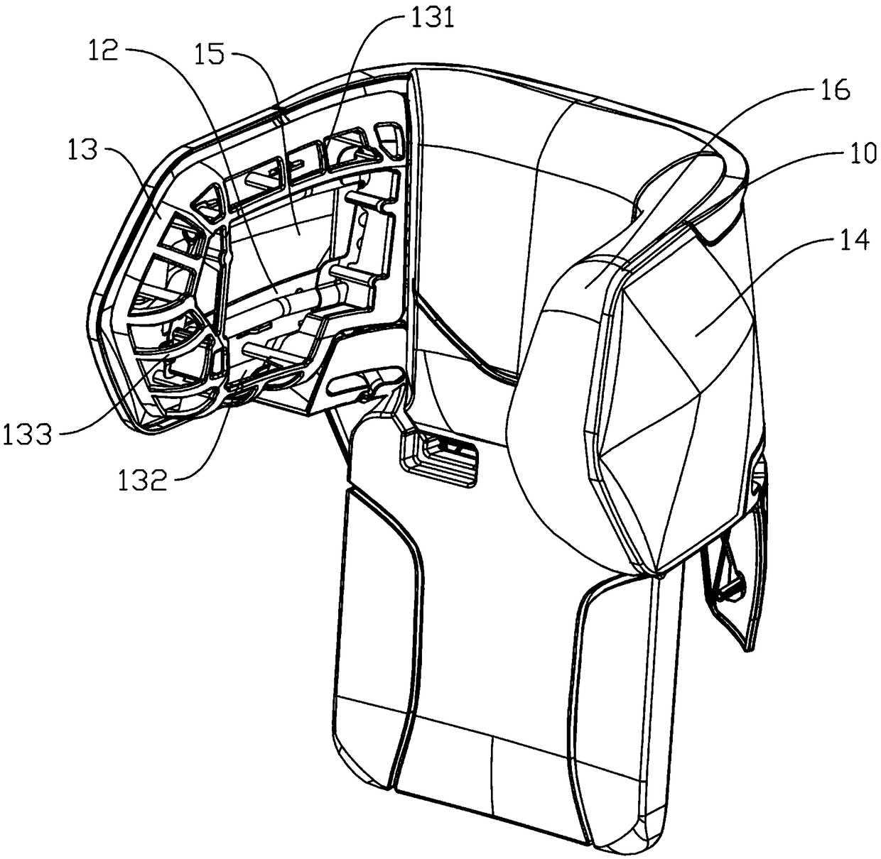
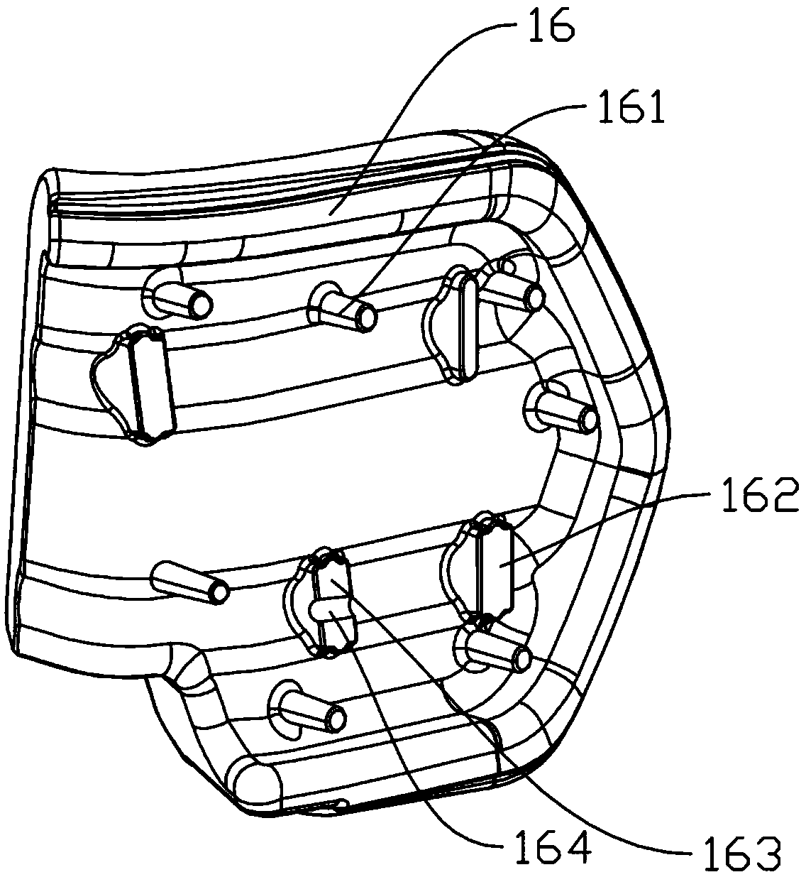
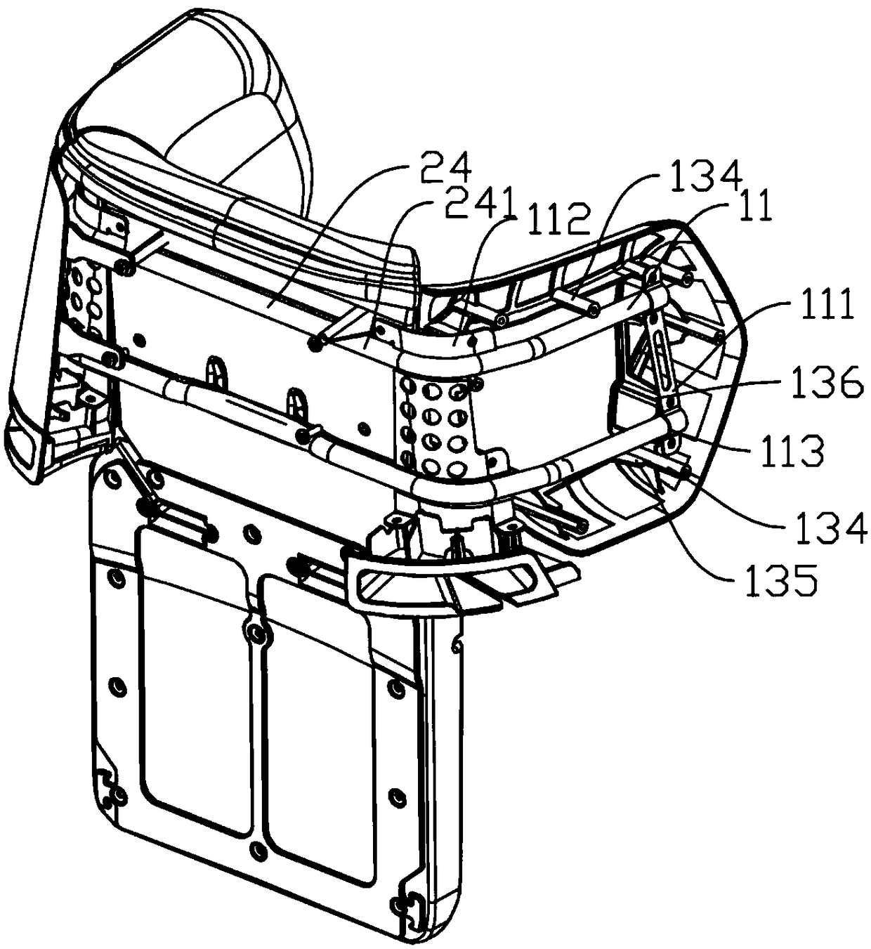
  • Head-neck flank damping structure, safety headrest and child safety seat
  • Head-neck flank damping structure, safety headrest and child safety seat
  • Head-neck flank damping structure, safety headrest and child safety seat

Examples


Embodiment Construction

[0036] Below, the present invention will be further described in conjunction with the accompanying drawings and specific implementation methods. It should be noted that, under the premise of not conflicting, the various embodiments described below or the technical features can be combined arbitrarily to form new embodiments. .

[0037] In the description of the present invention, it should be noted that for orientation words, such as the term "center", "horizontal", "longitudinal", "length", "width", "thickness", "upper", "lower" , "Front", "Back", "Left", "Right", "Vertical", "Horizontal", "Top", "Bottom", "Inner", "Outer", "Clockwise", "Counterclockwise " and other indication orientations and positional relationships are based on the orientations or positional relationships shown in the drawings, and are only for the convenience of describing the present invention and simplifying the description, rather than indicating or implying that the device or element referred to must ...


PUM


Abstract

The invention discloses a head-neck flank damping structure, a safety headrest and a child safety seat. The head-neck flank damping structure comprises a flank supporting skeleton, a flank supportingpiece, a damping mechanism, a protecting cover and an energy absorbing piece; the flank supporting skeleton is connected with a headrest skeleton, the flank supporting piece is connected with the headrest skeleton, and the damping mechanism is arranged on the inner side of the flank supporting skeleton and comprises a frame structure arranged around and a damping groove formed in the frame structure; the protecting cover is arranged outside the flank supporting piece and connected with the flank supporting piece; and the inner side of the damping mechanism is covered with the energy absorbingpiece, a buffering cavity is formed between the protective cover and the flank supporting piece, and the buffering cavity communicates with the damping groove. The head-neck flank damping structure has the advantages that deformation of the energy absorbing piece is larger through forming of the damping groove, and the situation that the head hits a hard plate behind the energy absorbing piece, consequently, buffering is insufficient, and damage is caused is avoided.

Description

technical field [0001] The invention relates to the field of child safety seats, in particular to a head and neck side wing shock absorbing structure, a safety headrest and a child safety seat. Background technique [0002] At present, a safety seat is a seat specially designed for children of different weights or ages, installed in a car, and can effectively improve the safety of children in a car. Many existing car accidents are caused by side impacts, and most of the child safety seats on the market do not have side impact protection devices. When side impacts occur, they often cannot protect the children seated well. There are also some producers who have produced child safety seats with side protection, such as the patent: The side protection structure (publication number: CN204749903U) of a child safety seat for cars comprises a side wing foam board, a reverse side collision frame and an anti-side collision foam board, but the reverse side The impact frame is in the s...

Claims


Application Information

Patent Timeline
IPC IPC(8): B60N2/28
CPCB60N2/2851B60N2/2872B60N2/2884
Inventor 钱建洪袁剑洪裘杭建陈凯新沈朝阳
Owner BUTONG SAFETY TECH (NINGBO) CO LTD
Learn More