Tensioner for electric power dispatching grid construction

A technology of power dispatching and stretching machine, which is applied in mechanical equipment, thin material handling, gear lubrication/cooling, etc., can solve the problems of increased centrifugal force of conveying wheel, messy cables falling off, and high transmission line speed, and can prevent the speed too fast effect

Inactive Publication Date: 2020-07-24
嘉兴市中法天线实业有限公司
View PDF6 Cites 2 Cited by
  • Summary
  • Abstract
  • Description
  • Claims
  • Application Information

AI Technical Summary

Problems solved by technology

[0002] The stretcher for power dispatching grid construction is a kind of equipment used for grid construction. It is aimed at the storage and release of cables, making grid construction more convenient. However, when the existing equipment is in use, due to the rotation of the conveying wheel When it is used, inertia will be generated, which will cause the centrifugal force of the conveying wheel to increase and the speed to increase, which will easily cause the speed of the conveying wheel to be too fast, which will cause the speed of the conveying line to be too high, and the cable will fall messy. At the same time, the conveying wheel is used for a period After a period of time, you need to add lubricating fluid to the wheel shaft, but if there are still cables on the wheel shaft, you need to drain the cables before adding lubricating oil, and then add cables, this method is time-consuming and laborious

Method used


Image

  • Tensioner for electric power dispatching grid construction
  • Tensioner for electric power dispatching grid construction
  • Tensioner for electric power dispatching grid construction

Examples


Embodiment

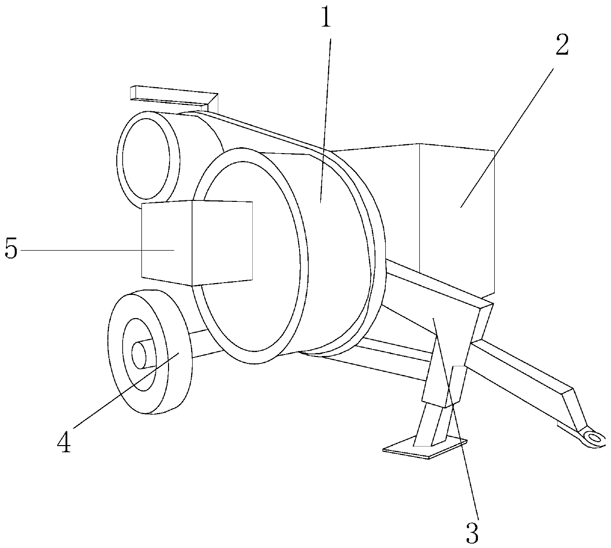
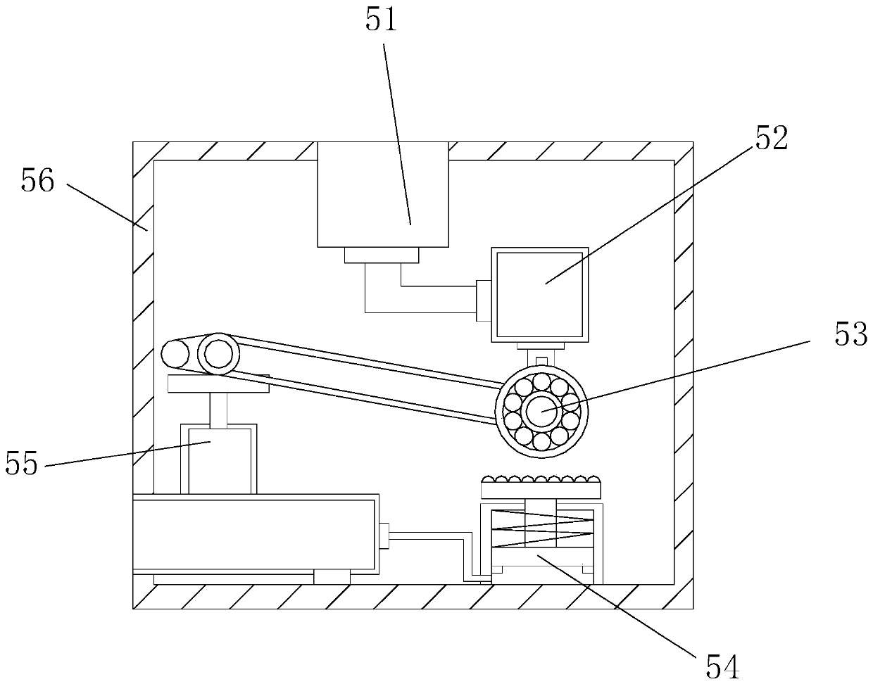
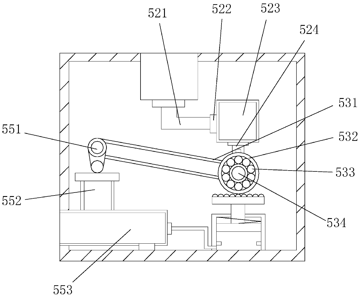
[0026] see Figure 1-Figure 7, the present invention provides a stretcher for power dispatching power grid construction, its structure includes a conveying wheel 1, a control box 2, a support frame 3, a roller 4 and an axle box 5, the conveying wheel 1 is arranged at the front end of the control box 2, and two The bottom end of the control box 2 is welded to the top of the support frame 3, the roller 4 is located under the axle box 5, the rear end of the axle box 5 is located at the front end of the conveying wheel 1, and the two The axle box 5 includes a filling mechanism 51, a lubrication dripping mechanism 52, a rotating connection shaft assembly 53, a speed reduction mechanism 54, a speed detection mechanism 55 and a casing 56, and the top of the filling mechanism 51 is connected to the top of the casing 56. Welded together, the lubricating dripping mechanism 52 is located directly above the rotating connection shaft assembly 53, and the two are movably connected, the redu...


PUM


Abstract

The invention discloses a traction machine for electric power dispatching power grid construction. The traction machine structurally comprises a conveying wheel, a control box, a support frame, a rolling wheel and a shaft box, wherein the conveying wheel is arranged at the front end of the control box and is movably connected with the control box, the bottom end of the control box is welded to thetop end of the support frame, the rolling wheel is located below the shaft box, the rear end of the shaft box is arranged at the front end of the conveying wheel, and the shaft box is movably connected with the conveying wheel. According to the traction machine, partial structure of the traction machine is improved, the rotating speed of the traction machine can be detected through the rotating shaft of the conveying wheel, so that when the rotating speed is too high, the speed is limited, so that the phenomenon that cables fall off and become disorderly due to the fact that the wire conveying speed of the conveying wheel is too fast is prevented, meanwhile, the adding mode of wheel shaft lubricating fluid is improved, so that when the wheel shaft lubricating fluid is added, the phenomenon that the cables are disassembled for adding the wheel shaft lubricating fluid and then installed is avoided, so that the traction machine is more convenient to use.

Description

technical field [0001] The invention relates to the field of stretching machines, in particular to a stretching machine for power dispatching power grid construction. Background technique [0002] The stretcher for power dispatching grid construction is a kind of equipment used for grid construction. It is aimed at the storage and release of cables, making grid construction more convenient. However, when the existing equipment is in use, due to the rotation of the conveying wheel When it is used, inertia will be generated, which will cause the centrifugal force of the conveying wheel to increase and the speed to increase, which will easily cause the speed of the conveying wheel to be too fast, which will cause the speed of the conveying line to be too high, and the cable will fall messy. At the same time, the conveying wheel is used for a period After a period of time, it is necessary to add lubricating fluid to the wheel shaft, but as there is also a cable on the wheel shaf...

Claims


Application Information

Patent Timeline
Patent Type & Authority Patents(China)
IPC IPC(8): F16H57/04B65H51/06
CPCB65H51/06B65H2701/34F16H57/0434
Inventor 林庆伟
Owner 嘉兴市中法天线实业有限公司
Why Eureka
Try Eureka