Wire routing structure and busbar module

A bus bar module and bus bar technology, applied in structural parts, cell structure combinations, circuits, etc., can solve problems such as jumping out of detection lines

Active Publication Date: 2019-01-29
YAZAKI CORP
View PDF8 Cites 2 Cited by
  • Summary
  • Abstract
  • Description
  • Claims
  • Application Information

AI Technical Summary

Problems solved by technology

As a result, the detection wire may jump out of the wire routing groove

Method used


Image

  • Wire routing structure and busbar module
  • Wire routing structure and busbar module
  • Wire routing structure and busbar module

Examples


Embodiment Construction

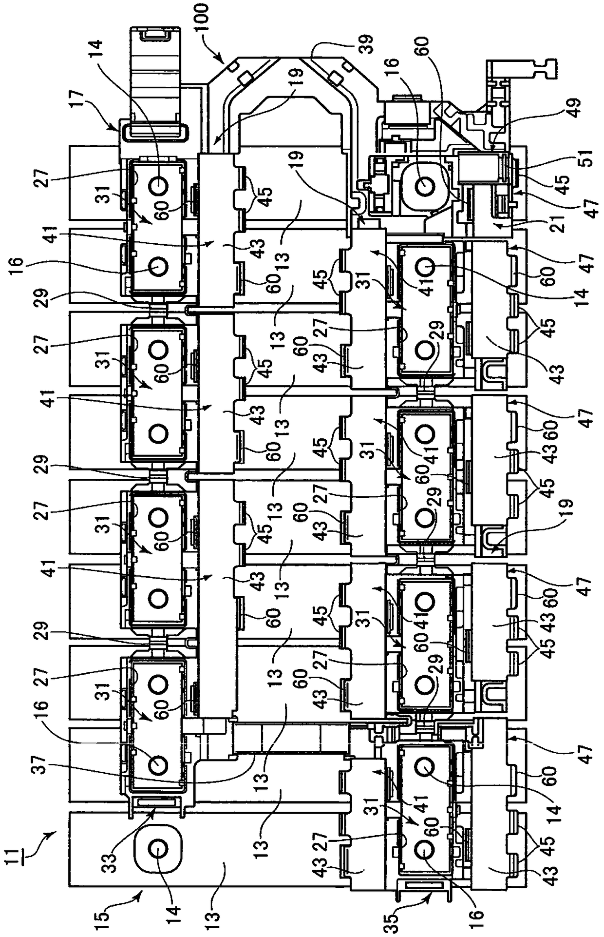
[0039] Hereinafter, the embodiments will be described with reference to the drawings. figure 1 is a schematic plan view of the battery pack 11 equipped with the bus bar module 100 having the wire routing structure according to the embodiment.

[0040] Such as figure 1 As shown, the wire routing structure according to the embodiment will be applicable to the bus bar module 100 . The bus bar module 100 is attached to an assembled battery 15 in which a plurality of single cells 13 are arranged adjacent to each other. The bus bar module 100 and the assembled battery 15 constitute the battery pack 11 .

[0041] In the embodiment, each unit cell 13 is shaped substantially in a plate shape, and has a positive electrode 14 and a negative electrode 16 at both ends in the length direction of a top surface which is a rectangular surface. Although in the embodiment, the positive electrode 14 and the negative electrode 16 are shaped substantially in a bolt shape, the present invention i...


PUM


Abstract

A wire routing structure includes a case, a wire routing groove formed in the case, a first wire accommodated in the wire routing groove, a second wire one end of which a connection terminal is attached, and a hinge cover connected to the case via a hinge portion. The hinge cover includes a wire holding portion that holds the second wire. The hinge portion positions in an opposite side of the connection terminal while interposing the first wire between the hinge portion and the connection terminal, and positioned below the second wire.

Description

[0001] Cross References to Related Applications [0002] This application is based on and claims priority from Japanese Patent Application No. 2017-141880 filed on July 21, 2017, the entirety of which is incorporated herein by reference. technical field [0003] The invention relates to a wire layout structure and a bus bar module. Background technique [0004] An assembled battery in which a plurality of cells are connected to each other in series or in parallel is installed in, for example, an electric vehicle or a hybrid electric vehicle. According to the prior art, in an assembled battery of a vehicle, the positive poles and negative poles of adjacent single cells are connected to each other through a plurality of bus bars. The common electrodes at both ends of the assembled battery are electrically connected to the power supply terminals (connection terminals) at the ends of the power supply lines connected to the load. These bus bars and power terminals are held in a...

Claims


Application Information

Patent Timeline
Patent Type & Authority Applications(China)
IPC IPC(8): H01M2/20H01M50/176H01M50/209H01M50/227H01M50/244H01M50/271H01M50/296H01M50/298H01M50/507H01M50/55H01M50/553H01M50/569
CPCH01M50/227H01M50/553H01M50/55H01M50/244H01M10/48H01M50/176H01M50/507H01M50/209H01M50/298H01M50/569H01M50/271H01M50/296H01M10/486H01M10/425H01M2010/4278Y02E60/10
Inventor 桥本悠希
Owner YAZAKI CORP
Why Eureka
Try Eureka