Reciprocating stirring mixer

A mixing and reciprocating technology, which is applied in mixers, shaking/oscillating/vibrating mixers, dissolving, etc., can solve the problems of low work efficiency, weak operation prompt effect, poor product quality, etc., and achieve high work efficiency and prompt Strong effect, good for monitoring effect

Active Publication Date: 2019-02-01
天门市格韵无纺布有限公司
View PDF8 Cites 2 Cited by
  • Summary
  • Abstract
  • Description
  • Claims
  • Application Information

AI Technical Summary

Problems solved by technology

[0005] The purpose of the present invention is to overcome the defects and problems of low work efficiency, poor product quality, and weak operation prompt effect existing in the prior art, and provide a high work efficiency, good product quality, and strong operation prompt effect. reciprocating mixing mixer

Method used


Image

  • Reciprocating stirring mixer
  • Reciprocating stirring mixer
  • Reciprocating stirring mixer

Examples


Embodiment 1

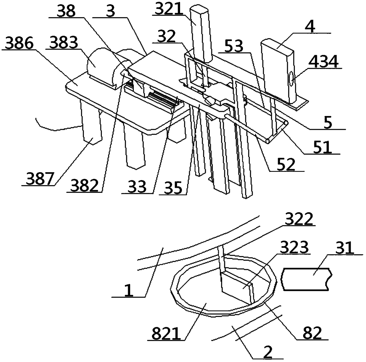
[0050] see Figure 1 to Figure 8, a reciprocating stirring mixer, comprising a particle adding device 3, an operation indicating device 4, a fixed flat disk 1 and a rotating flat disk 2, the fixed flat disk 1 and the rotating flat disk 2 are arranged in parallel up and down, and the rotating flat disk No. 2 groove 82 is arranged on the disk surface of 2; the particle adding device 3 includes an external adding unit 31, a lifting unit 32 and a horizontal drive unit 33, and the discharge port of the external adding unit 31 communicates with the stirring chamber 821, so The lifting unit 32 includes a lifting motor 321, a lifting rod 322 and an agitator 323. The lifting motor 321 is set higher than the fixed flat plate 1. The output end of the lifting motor 321 is connected with the top of the lifting rod 322, and the bottom end of the lifting rod 322 passes through After the flat plate 1 is fixed, it is connected with the stirring member 323, the stirring member 323 is located di...

Embodiment 2

[0052] Basic content is the same as embodiment 1, the difference is:

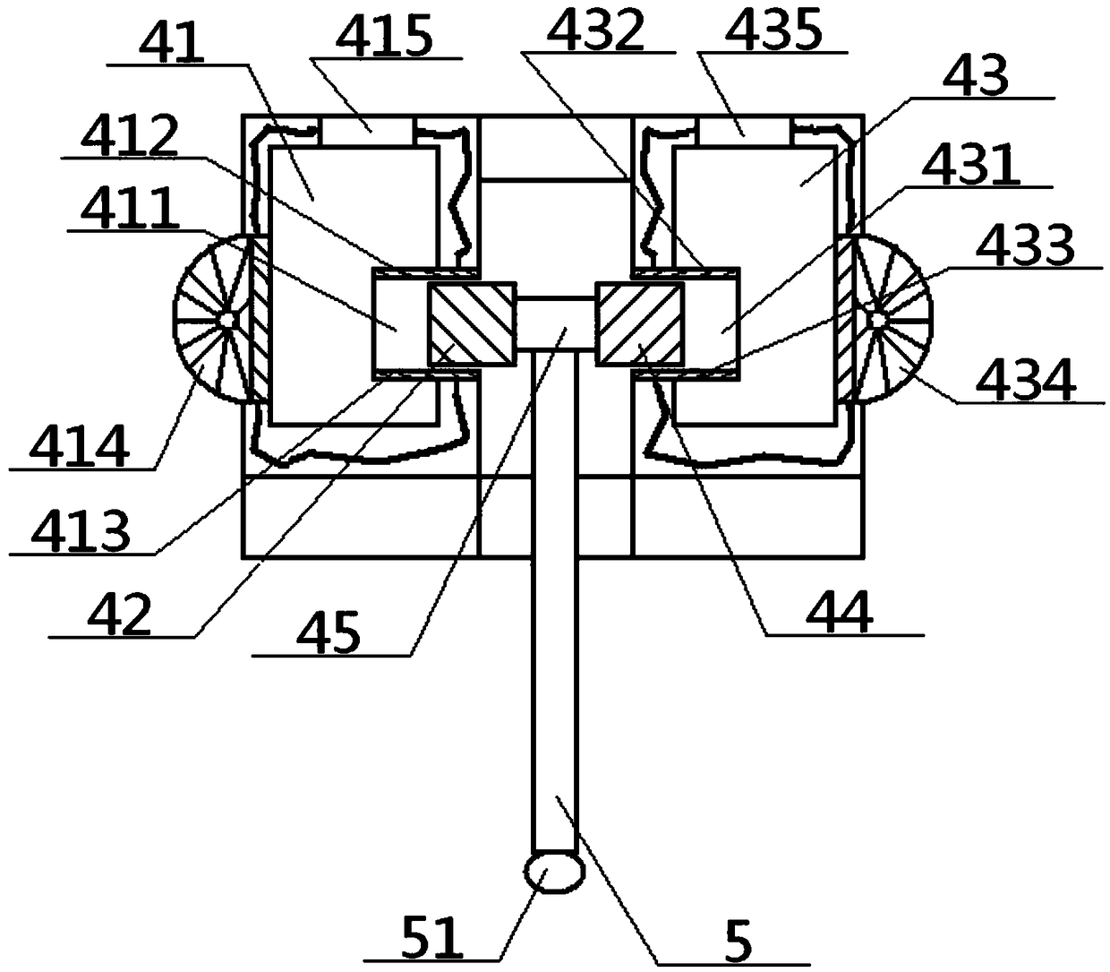
[0053] The return indication unit 41 also includes a return indicator light 414, a left power supply box 415, an upper left power supply piece 412 and a lower left power supply piece 413. 413 is connected to the circuit, and the left upper energization sheet 412 and the left lower energization sheet 413 are clipped up and down to form a return energization groove 411, and the return energization groove 411 is inserted into the outer end of the left switching sheet 42 sandwiched therebetween; the forward indicating unit 43 It also includes a forward indicator light 434, a right power supply box 435, an upper right electrification sheet 432 and a lower right electrification sheet 433, and the upper right electrification sheet 432 is connected with the lower right electrification sheet 433 successively through the right power supply box 435, the forward indicator lamp 434 Circuit connection, the upper right en...

Embodiment 3

[0055] Basic content is the same as embodiment 1, the difference is:

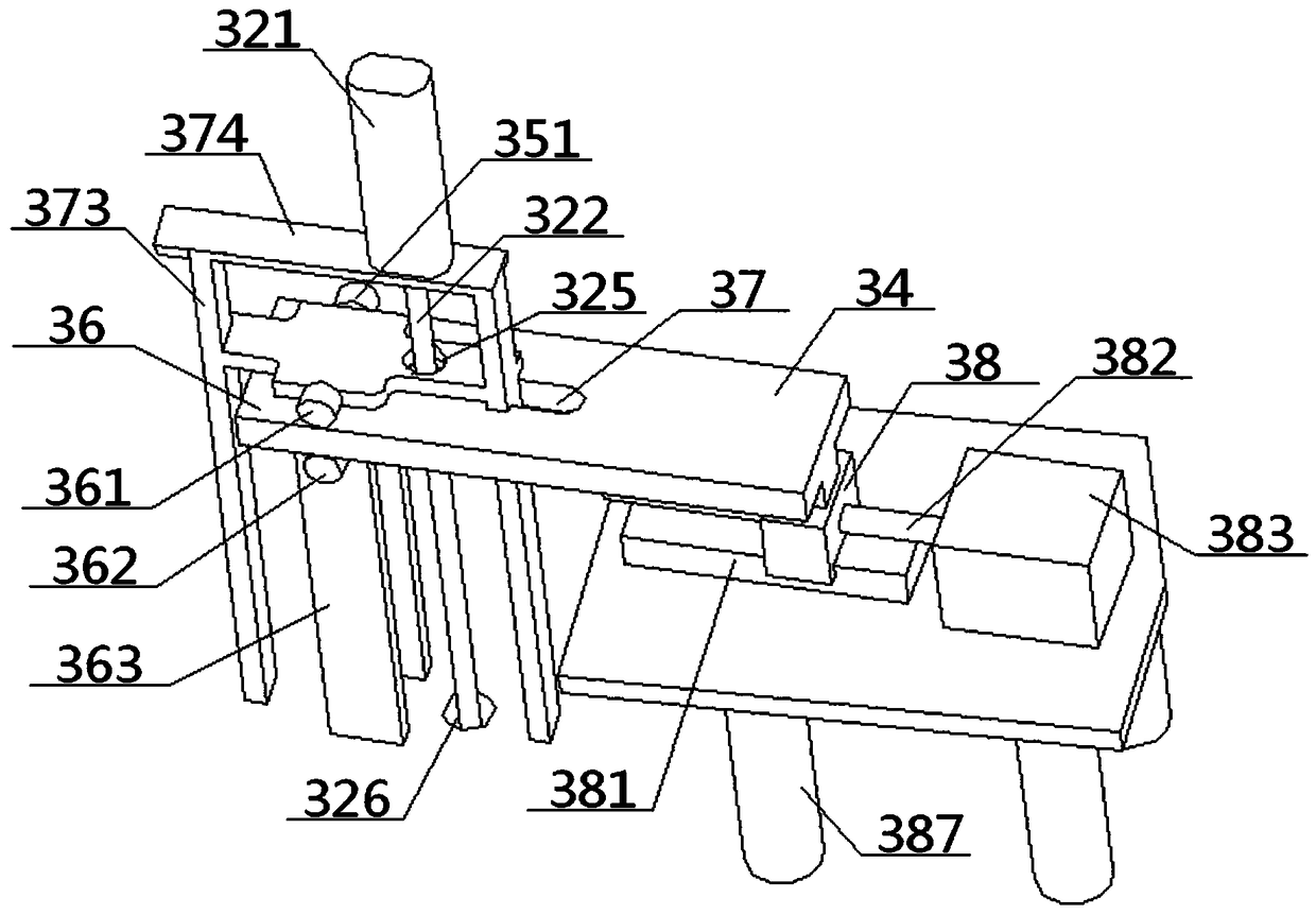
[0056] The transverse drive unit 33 also includes a transverse drive plate 34, a front transverse drive slide bar 35 and a rear transverse drive slide bar 36. Drive the inner end of slide bar 36 to be connected, and the outer end of front transverse drive slide bar 35, rear transverse drive slide bar 36 extends outward along lateral direction, and the inner surface of rear transverse drive slide bar 36 is provided with drive tooth bar 364 to be connected with transverse drive slide bar 36. The outer periphery of drive table 324 is meshed, and the front cross drive slide bar 35, the cross drive plate 34, and the rear cross drive slide bar 36 together form a sliding cavity 37 with one-way opening. The left support set in the slide cavity 37 The middle part of the bar 371 is connected with the middle part of the right support bar 373 through the middle support plate 372, and the front and rear side parts of th...


PUM


Abstract

The invention relates to a reciprocating stirring mixer, which comprises an operation indicating device and a particle adding device, the operation indicating device comprises a left / right switching sheet and a return / forward indicating unit, the particle adding device comprises an external adding unit, an elevating unit and a horizontal driving unit, a discharging port of the external adding unitis communicated to a stirring chamber, the bottom end of an elevating rod in the elevating unit is connected to a stirring member located directly above the stirring chamber after passing through a fixed flat plate, a portion of the lifting rod located between the elevating motor and the fixed flat plate is sleeved with a cross-drive bench that is reciprocally driven in a lateral direction with amiddle portion of the horizontal drive unit, the outer end portion of the horizontal drive unit is connected to a middle switching rod through front and rear switching rods, and the middle switchingrod is connected to the inner ends of the left and right switching sheets through the rear switching rod, and the outer ends of the left and right switching sheets are respectively inserted and matched with the returning and forward energizing slots in the return / forward indicating unit. The design of the reciprocating stirring mixer not only has high work efficiency, good product quality, but also has strong operation prompt effect and high safety.

Description

technical field [0001] The invention relates to a mixing device, in particular to a reciprocating stirring mixer, which is particularly suitable for improving product quality and work efficiency, and enhancing the operation prompting effect. Background technique [0002] At present, with the increasing development of the industry, the operation of making a particle layer on the liner or the products of setting the particle layer on the liner are also increasing, and are used in various fields, such as the grinding wheel as a grinding tool (the grinding wheel can be Through high-speed rotation during use, operations such as rough grinding, semi-finishing, fine grinding, grooving, and cutting of various surfaces of metal or non-metallic workpieces have been widely used in various aspects of the grinding field), grinding wheels Including the top layer, the bottom layer and the particle layer sandwiched between them, it is necessary to set the particle layer on the single-layer ...

Claims


Application Information

Patent Timeline
Patent Type & Authority Applications(China)
IPC IPC(8): B01F13/10B01F11/00
CPCB01F31/441B01F33/80514
Inventor 张智明徐巧赖梓龙陈博雅段耀帅梅顺齐姬巧玲
Owner 天门市格韵无纺布有限公司
Why Eureka
Try Eureka