
Movable base of machine tool

A technology for moving bases and machine tools, applied in the field of machine tools, can solve problems such as inconvenient adjustment, inconvenient movement of machine tools, inconvenient screw rotation, etc., and achieve the effect of easy movement

Inactive Publication Date: 2019-02-01
台州多凯工业设计有限公司
View PDF1 Cites 2 Cited by
  • Summary
  • Abstract
  • Description
  • Claims
  • Application Information

AI Technical Summary

Problems solved by technology

No matter what type of machine tool it is, it is inseparable from the base of the machine tool. During the use of the machine tool, it is often necessary to move the machine tool according to different processing requirements. The general machine tool is heavy and inconvenient to move
[0003] Chinese patent CN105397502A discloses a CNC machine tool base. The flatness of the base body can be easily adjusted through the design of the screw, and the base is supported by the feet. Movement: Although the structure of the screw can support the machine tool, it is not convenient to rotate the screw when the screw is in contact with the ground, it is inconvenient to adjust, and the movement of the machine tool is not convenient enough

Method used


Image

  • Movable base of machine tool
  • Movable base of machine tool
  • Movable base of machine tool

Examples


Embodiment Construction

[0028] In order to enable those skilled in the art to better understand the solutions of the present invention, the technical solutions in the embodiments of the present invention will be clearly and completely described below in conjunction with the drawings in the embodiments of the present invention. Obviously, the described embodiments are only It is a part of embodiments of the present invention, but not all embodiments. Based on the embodiments of the present invention, all other embodiments obtained by persons of ordinary skill in the art without making creative efforts shall fall within the protection scope of the present invention.

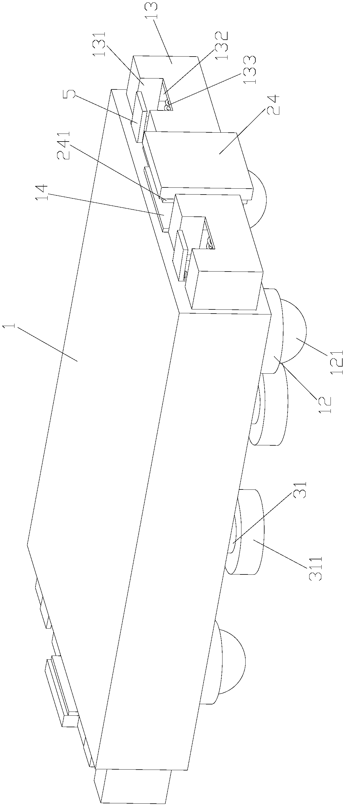
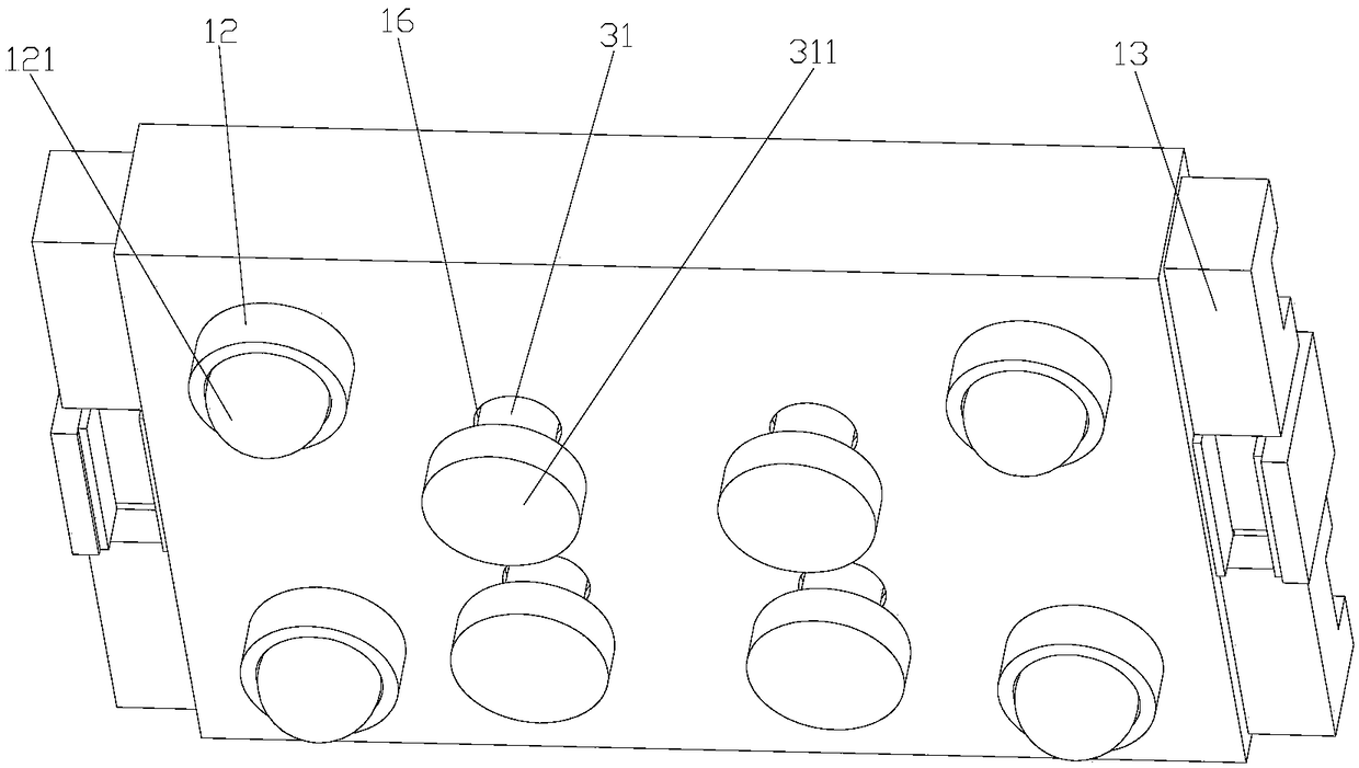
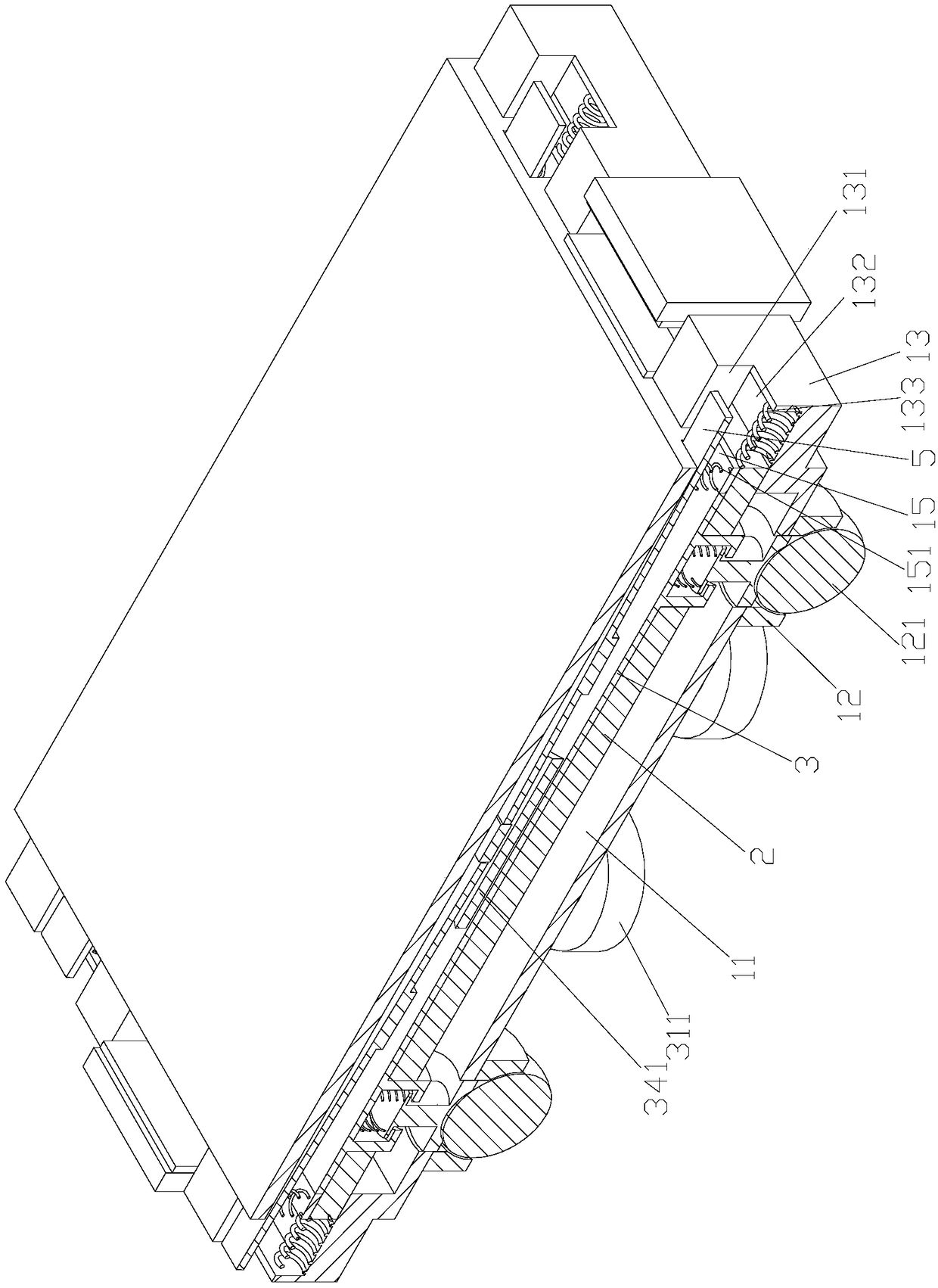
[0029] Such as Figure 1-12 As shown, a mobile base of a machine tool includes a support plate 1, a plurality of installation tubes 12 arranged at the bottom of the support plate 1, and rollers 121 arranged in the installation tubes 12. The rollers 121 are spherical structures, so The roller 121 is rotatably connected to the installation...


PUM


Abstract

The invention discloses a movable base of a machine tool. The movable base comprises a supporting plate, a plurality of mounting tubes arranged on the bottom of the supporting plate, and rollers arranged in the mounting tubes, wherein the rollers are of spherical structures; the rollers can be rotatably connected in the mounting tubes; a mounting cavity is arranged in the supporting tube; a mounting plate is arranged in the mounting cavity; a plurality of supporting rods are arranged on the bottom of the mounting plate; supporting blocks are arranged on bottoms of the supporting rods; a plurality of first through holes matched with the supporting rods are formed in the bottom of the mounting cavity; the supporting rods are arranged in the first through holes in a penetrating mode; a lifting assembly for driving the mounting plate to perform lifting motion is arranged above the mounting plate; the mounting cavity communicates with the outside of the supporting plate; and a fixed plate which is matched with the supporting rod is arranged in the mounting cavity in a penetrating mode.

Description

technical field [0001] The invention belongs to the field of machine tools, and in particular relates to a mobile base of a machine tool. Background technique [0002] Machine tool is an important basic equipment of today's industry, and it is a means of modernizing the production of pillar industries such as automobiles, motorcycles, aerospace, molds, machine tools, and electronics. As an important part of the machine tool, the base of the machine tool directly determines the machining accuracy and working life of the machine tool. No matter what type of machine tool it is, it is inseparable from the base of the machine tool. During the use of the machine tool, it is often necessary to move the machine tool according to the different processing requirements. The general machine tool is heavy and inconvenient to move. [0003] Chinese patent CN105397502A discloses a CNC machine tool base. The flatness of the base body can be easily adjusted through the design of the screw, ...

Claims


Application Information

Patent Timeline
Patent Type & Authority Applications(China)
IPC IPC(8): B23Q1/01
CPCB23Q1/015
Inventor 陈豪吴高国江小兵
Owner 台州多凯工业设计有限公司
Learn More