Scrap removal structure of machine tool

A machine tool and flute technology, which is applied to metal processing machinery parts, maintenance and safety accessories, metal processing equipment, etc., can solve the problems such as difficulty in discharging iron filings, achieve production cost saving, reasonable structural design, and improve work efficiency Effect

Inactive Publication Date: 2019-02-01
徐州优尚精密机械制造有限公司
View PDF7 Cites 10 Cited by
  • Summary
  • Abstract
  • Description
  • Claims
  • Application Information

AI Technical Summary

Problems solved by technology

[0003] Purpose of the invention: The purpose of the invention is to provide a chip removal structure for machine tools, which solves the problem that iron chips are difficult to discharge during the production and processing of machine tools

Method used


Image

  • Scrap removal structure of machine tool
  • Scrap removal structure of machine tool
  • Scrap removal structure of machine tool

Examples


Embodiment

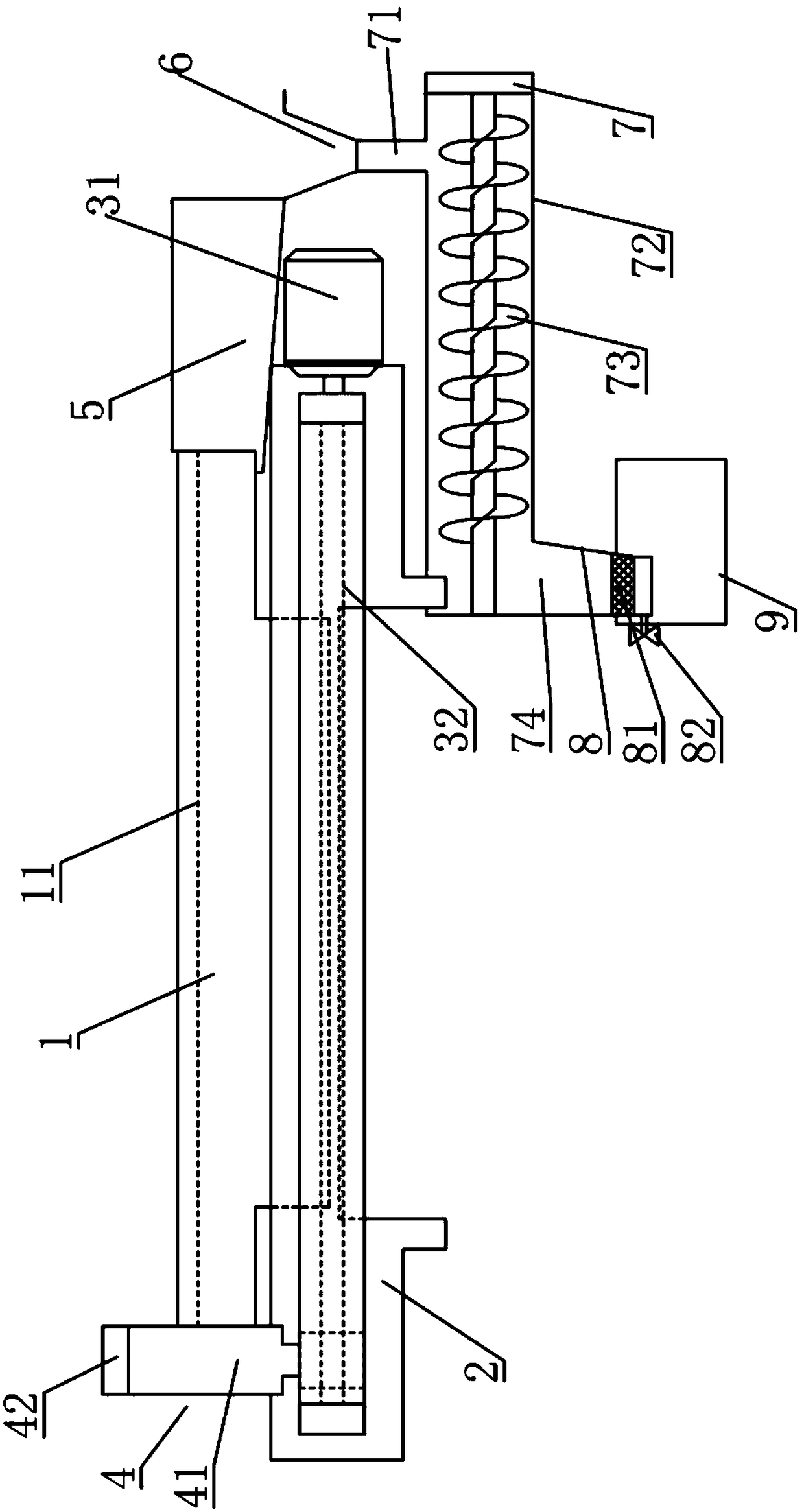
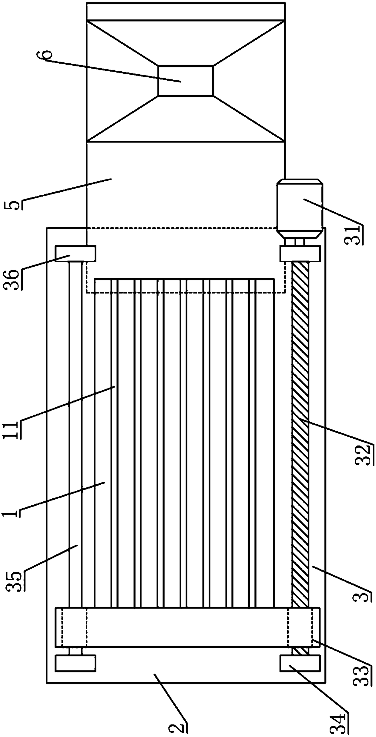
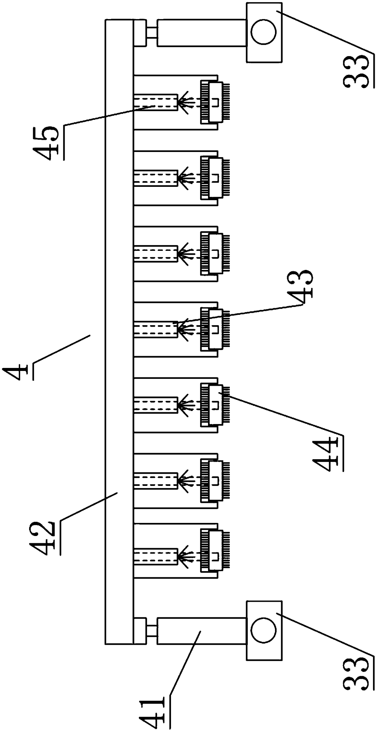
[0026] like figure 1 , 2 The shown chip removal structure of the machine tool includes upper work surface 1, lower work surface 2, drive assembly 3, chip removal assembly 4, chip removal groove 5, hopper 6, material guide assembly 7, chip storage hopper 8 and cleaning fluid Collection box 9, the upper work surface 1 is set above the lower work surface 2, the drive assembly 3 is set on the lower work surface 2, the lower end of the chip removal assembly 4 is set on the drive assembly 3, and the chip removal assembly 4 It is erected above the upper work surface 1, the chip removal groove 5 is set at one end of the upper work surface 1, the hopper 6 is set at the lower end of the chip removal groove 5, and one end of the material guide assembly 7 is set at the hopper 6, and the other end of the material guide assembly 7 away from the material receiving hopper 6 is connected to the chip storage hopper 8, and the cleaning liquid collection box 9 is arranged below the chip storage ...


PUM


Abstract

The invention discloses a scrap removal structure of a machine tool, and belongs to the technical field of machine tool equipment. The scrap removal structure of the machine tool comprises an upper working table board, a lower working table board, a driving assembly, a scrap removal assembly, a scrap removal groove, a material receiving hopper, a material guiding assembly, a scrap storage hopper and a cleaning fluid collection box; the lower end of the scrap removal assembly is arranged on the driving assembly, and the scrap removal assembly is erected above the upper working table board; andthe material receiving hopper is arranged at the lower end of the scrap removal groove, one end of the material guiding assembly is arranged at the lower end of the material receiving hopper, and theother end, away from the material receiving hopper, of the material guiding assembly is connected to the scrap storage hopper. According to the scrap removal structure of the machine tool, through thearrangement of the scrap removal assembly, iron scraps on the working table boards and the groove of the machine tool can be efficiently cleared, and the iron scraps can be guided into the scrap storage hopper through the scrap removal groove, the material receiving hopper and the material guiding assembly, and the iron scraps are stored in the scrap storage hopper; and due to the fact that cleaning fluid is needed by the scrap removal assembly to wash the working table boards, the cleaning liquid collection box is arranged below the scrap storage hopper, and therefore the cleaning fluid canbe recycled.

Description

technical field [0001] The invention belongs to the technical field of machine tool equipment, and in particular relates to a chip removal structure of a machine tool. Background technique [0002] Industry is a major industry in my country. With the improvement of processing technology, the use of CNC machine tools has become very common. When CNC machine tools are processing mechanical parts, a large amount of debris will be generated due to drilling or grinding steps. On the worktable, or even fall into the T-slot of the worktable, it needs to be cleaned in time in order to maintain the normal use of the CNC machine tool. The traditional method of chip removal is to make the chips slide along the chip removal inclined plate on the bed to the special belt-type chip conveyor under the bed by its own gravity, and then transport it to the chip collector outside the machine tool through the belt of the chip conveyor to reach the machine tool. However, due to the uneven edge of...

Claims


Application Information

Patent Timeline
Patent Type & Authority Applications(China)
IPC IPC(8): B23Q11/00
CPCB23Q11/005
Inventor 王洪年
Owner 徐州优尚精密机械制造有限公司
Why Eureka
Try Eureka