
High-efficiency aluminum material surface drawing device

A surface-drawing, high-efficiency technology, used in grinding/polishing safety devices, grinding machines, grinding/polishing equipment, etc., can solve the problem of excessive heat generation due to friction between the abrasive belt and the surface of the aluminum material, and the surface of the aluminum material cannot be drawn by the abrasive belt. , small area of ​​aluminum materials, etc., to achieve the effect of extending continuous working time, good drawing effect and high work efficiency

Inactive Publication Date: 2019-02-01
湖州市漾西电化有限公司
View PDF0 Cites 4 Cited by
  • Summary
  • Abstract
  • Description
  • Claims
  • Application Information

AI Technical Summary

Problems solved by technology

[0002] At present, some common aluminum surface drawing devices on the market usually carry out wire drawing on the aluminum surface by moving the rotating abrasive belt down and contacting the aluminum surface. Small size, low work efficiency; if a larger area of ​​aluminum is drawn at one time, the contact between the abrasive belt and the surface of the aluminum is not complete, causing the problem that some aluminum surfaces cannot be drawn by the abrasive belt, and the drawing effect is poor ; and the friction between the abrasive belt and the surface of the aluminum material produces more heat, which is likely to cause a higher temperature of the equipment, and it is necessary to stop the machine frequently to cool down, which reduces the work efficiency
Therefore, the existing aluminum surface wire drawing device has the problems of low work efficiency and poor wire drawing effect

Method used


Image

  • High-efficiency aluminum material surface drawing device
  • High-efficiency aluminum material surface drawing device
  • High-efficiency aluminum material surface drawing device

Examples


Embodiment Construction

[0014] The present invention will be further described below in conjunction with the accompanying drawings and embodiments, but not as a basis for limiting the present invention.

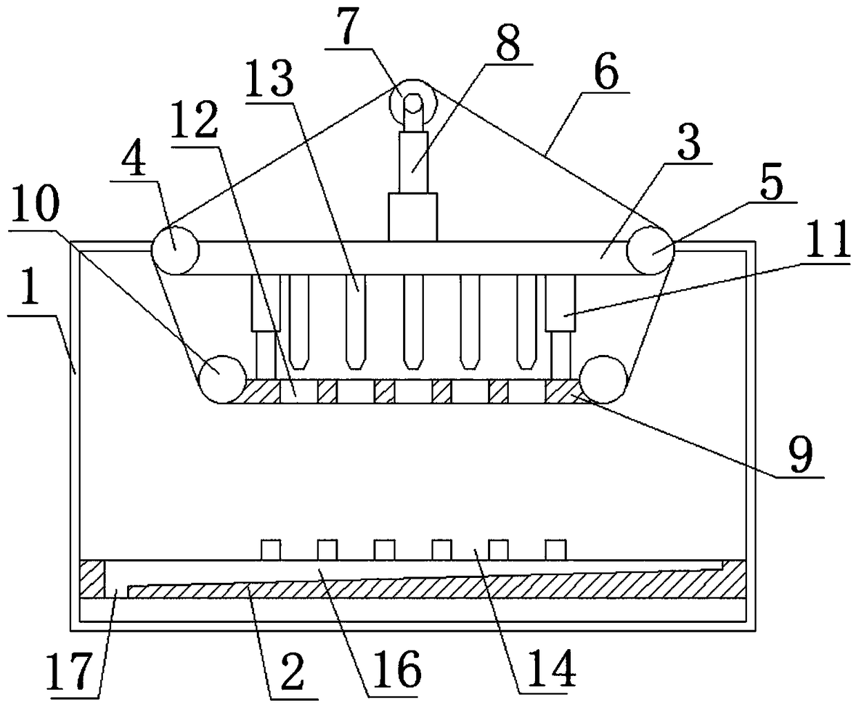
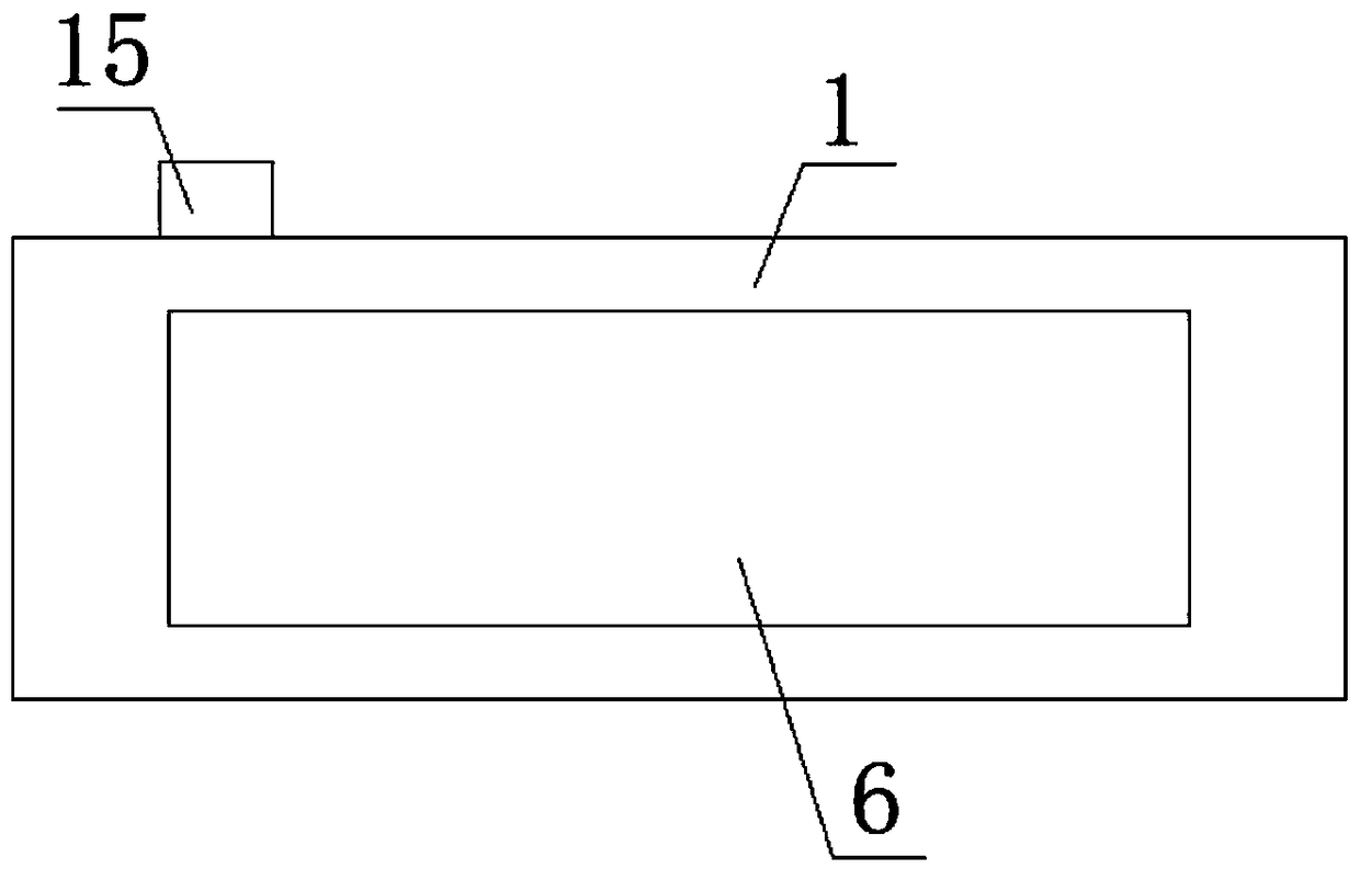
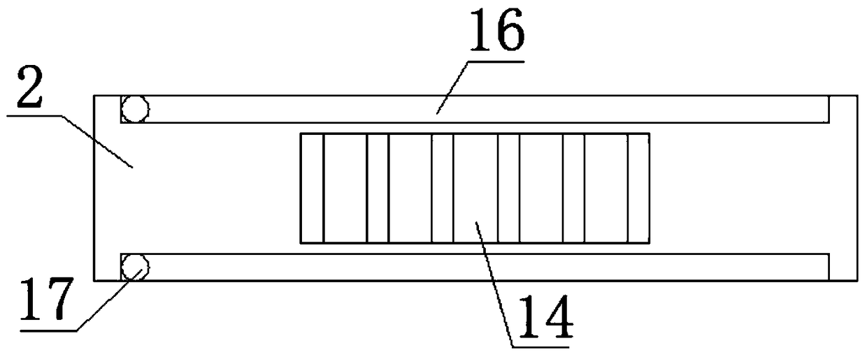
[0015] Example. High-efficiency aluminum surface drawing device, composed of Figures 1 to 3 As shown, a frame 1 is included, and a bottom plate 2 is arranged on the frame 1; a top plate 3 is arranged above the bottom plate 2, and the two ends of the top plate 3 are respectively connected with a driving roller 4 and a driven roller 5, and the driving roller 4 and the driven roller 5 is sleeved with an abrasive belt 6; a tension roller 7 is arranged above the top plate 3, and a first hydraulic cylinder 8 is connected between the tension roller 7 and the top plate 3, and the tension roller 7 is arranged in the abrasive belt 6; the top plate 3 and A pressing plate 9 is arranged between the bottom plates 2, and the pressing plate 9 is arranged in the abrasive belt 6; both sides of the pressing plate 9 ...


PUM


Abstract

The invention discloses a high-efficiency aluminum material surface drawing device. The high-efficiency aluminum material surface drawing device comprises a rack. A base plate is arranged on the rack.A top plate is arranged above the base plate. A driving roller and a driven roller are connected to the two ends of the top plate correspondingly. A sanding belt is connected to the driving roller and the driven roller in a sleeving manner. A tensioning roller is connected above the top plate through a first hydraulic cylinder and arranged inside the sanding belt. A pressing plate is arranged atthe position, between the top plate and the base plate, inside the sanding belt. Guiding rollers are connected to the two sides of the pressing plate correspondingly. A second hydraulic cylinder is connected to the pressing plate and the top plate. Multiple groove holes are formed in the pressing plate, wherein the groove holes are uniformly distributed. Multiple air nozzles are connected to the bottom end of the top plate, wherein the air nozzles are uniformly distributed. By means of the high-efficiency aluminum material surface drawing device, work efficiency is improved; and the high-efficiency aluminum material surface drawing device has the advantages that the drawing effect is good, environmental pollution is small, and resources are saved.

Description

technical field [0001] The invention relates to a metal surface wire drawing device, in particular to a high-efficiency aluminum material surface wire drawing device. Background technique [0002] At present, some common aluminum surface drawing devices on the market usually carry out wire drawing on the aluminum surface by moving the rotating abrasive belt down and contacting the aluminum surface. Small size, low work efficiency; if a larger area of ​​aluminum is drawn at one time, the contact between the abrasive belt and the surface of the aluminum is not complete, causing the problem that some aluminum surfaces cannot be drawn by the abrasive belt, and the drawing effect is poor ; And the friction between the abrasive belt and the surface of the aluminum material produces more heat, which easily causes the equipment to have a higher temperature. It is necessary to stop the machine frequently to cool down, which reduces the work efficiency. Therefore, the existing alumin...

Claims


Application Information

Patent Timeline
Patent Type & Authority Applications(China)
IPC IPC(8): B24B21/00B24B41/06B24B41/02B24B21/20B24B55/06B24B55/02
CPCB24B21/006B24B21/20B24B41/02B24B41/06B24B55/02B24B55/06
Inventor 钱顺妹
Owner 湖州市漾西电化有限公司
Learn More