Al technical title is built by PatSnap Al team. It summarizes the technical point description of the patent document.
A conveying mechanism, rocker-type technology, applied in the field of rocker-type triangular plate conveying mechanism, can solve the problems of unfavorable disassembly and maintenance, unfavorable installation and adjustment, large space occupation, etc., and achieve the effect of reducing manual intervention and being convenient and accurate
Pending Publication Date: 2019-02-01
杜克普爱华工业制造(上海)有限公司
View PDF0 Cites 2 Cited by
Summary
Abstract
Description
Claims
Application Information
AI Technical Summary
This helps you quickly interpret patents by identifying the three key elements:
Problems solved by technology
Method used
Benefits of technology
Problems solved by technology
[0002] The existing transmission structure is complex and takes up a lot of space, which is not conducive to installation and adjustment, and is not conducive to disassembly and maintenance
Method used
Image
Click on the blue label to locate the original text in one second.
Reading with bidirectional positioning of images and text.
Examples
Embodiment Construction
[0013] The technical solutions in the embodiments of the present invention will be clearly and completely described below in conjunction with the accompanying drawings in the embodiments of the present invention. Obviously, the described embodiments are only a part of the embodiments of the present invention, rather than all the embodiments. Based on the embodiments of the present invention, all other embodiments obtained by those of ordinary skill in the art without creative work shall fall within the protection scope of the present invention.
[0014] It should be noted that the embodiments of the present invention and the features in the embodiments can be combined with each other if there is no conflict.
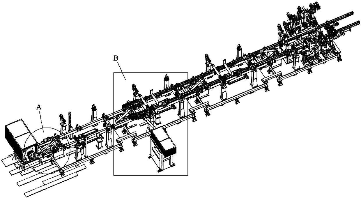
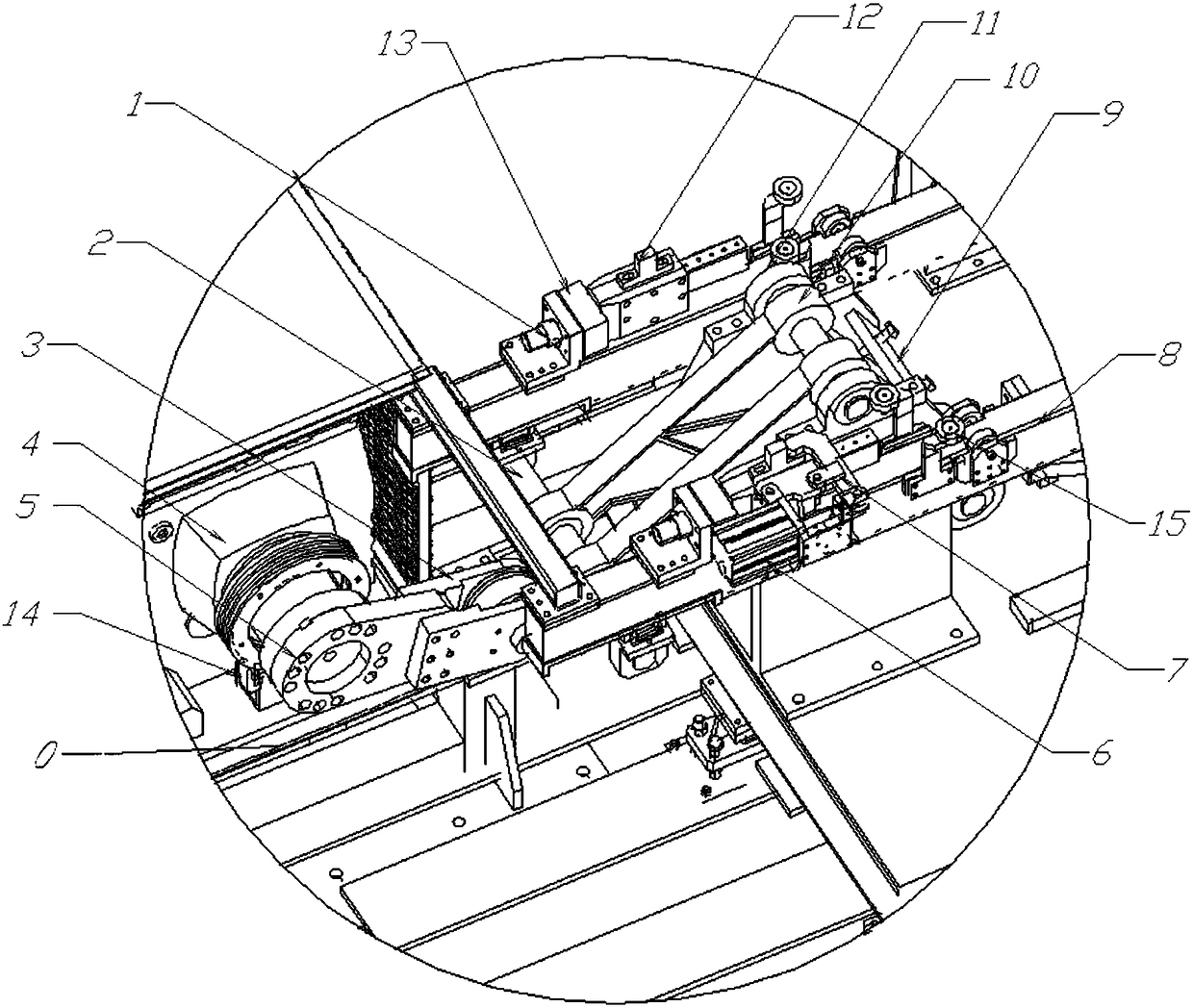
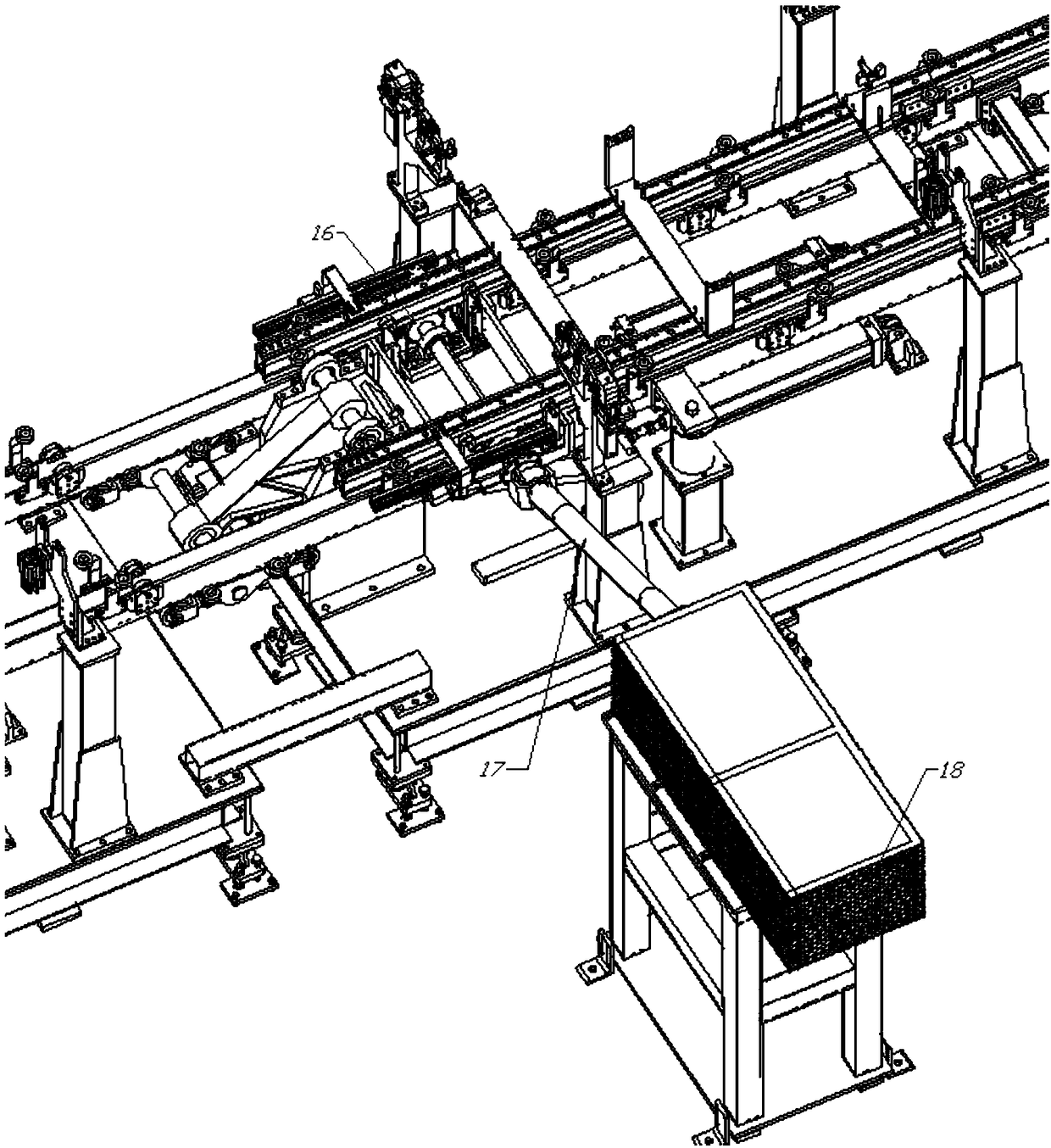
[0015] reference figure 1 , figure 2 with image 3 As shown, the rocker arm type triangular plate conveying mechanism of the present invention includes a frame 0, and a first motor 5, a buffer 2, a shaft 3, a connecting plate 4, a crankshaft connecting plate 6, a cylinder 7,...
PUM
Abstract
The invention relates to a novel rocker-type triangular plate conveying mechanism. The novel rocker-type triangular plate conveying mechanism comprises a frame, a first motor, a buffer, a shaft, a connecting shaft, a crankshaft connecting plate, a cylinder, a limiting rocker, a conveying rod, a stop block, a rocker-type triangular plate, a bearing seat, a conveying locking stop block, a travel switch, a guide wheel, a gear and a second motor, wherein the first motor, the buffer, the shaft, the connecting shaft, the crankshaft connecting plate, the cylinder, the limiting rocker, the conveying rod, the stop block, the rocker-type triangular plate, the bearing seat, the conveying locking stop block, the travel switch, the guide wheel, the gear and the second motor are arranged on the frame. The bearing seat is connected with the shaft to achieve rotation. The crankshaft connecting plate, the rocker-type triangular plate and the connecting plate are driven by the first motor to move upwards to achieve ejection or to move downwards to slow down when touching the travel switch, the cylinder moves, the limiting rocker is opened, and the second motor works; and the conveying rod is drivenby the guide wheel and the gear to move horizontally to slow down when touching the buffer and then to attached to the stop block to stop, the cylinder moves, the limiting rocker is pressed for conveying, and the stop block is locked. According to the whole novel rocker-type triangular plate conveying mechanism, the workpiece feeding position is made more accurate, and the workpiece conveying accuracy is ensured; and compared with a traditional conveying structure, human intervention is greatly reduced, and safety and reliability are ensured.
Description
Technical field [0001] The invention relates to a positioning conveying mechanism, in particular to a rocker arm type triangular plate conveying mechanism. Background technique [0002] The existing transmission structure is complicated, occupies a large space, is not conducive to installation and adjustment, and is not conducive to disassembly and maintenance. Summary of the invention [0003] In view of this, the purpose of the present invention is to provide a rocker type triangular plate conveying mechanism to solve the deficiencies in the prior art. [0004] In order to achieve the above objective, the objective of the present invention is achieved through the following technical solutions: [0005] Provided is a rocker arm type triangular plate conveying mechanism, including a frame, and a first motor, a buffer, a shaft, a connecting plate, a crankshaft connecting plate, a cylinder, a limit rocker arm, a conveying rod, and a limit block arranged on the frame , Rocker triangle ...
Claims
Application Information
Patent Timeline
Application Date:The date an application was filed.
Publication Date:The date a patent or application was officially published.
First Publication Date:The earliest publication date of a patent with the same application number.
Issue Date:Publication date of the patent grant document.
PCT Entry Date:The Entry date of PCT National Phase.
Estimated Expiry Date:The statutory expiry date of a patent right according to the Patent Law, and it is the longest term of protection that the patent right can achieve without the termination of the patent right due to other reasons(Term extension factor has been taken into account ).
Invalid Date:Actual expiry date is based on effective date or publication date of legal transaction data of invalid patent.