
Sewing machine

A sewing machine and reverse sewing technology, which is applied in the direction of sewing machine components, sewing machine control devices, sewing equipment, etc., can solve the problems affecting the stability of tight seams, jamming, and easy deflection, etc., so as to improve the stability of tight seams and improve Effects of service life and maintenance cost reduction

Active Publication Date: 2019-02-01
ZHEJIANG OCEAN UNIV
View PDF5 Cites 1 Cited by
  • Summary
  • Abstract
  • Description
  • Claims
  • Application Information

AI Technical Summary

Problems solved by technology

[0004] However, the above-mentioned structure still has the following defects: when performing tight seaming, the specific structure is to drive the limit rod to move between the connecting part and the buffer part in the backstitching mechanism through the tight seam electromagnet and the corresponding transmission mechanism, The contact between the positioning rod and the buffer part limits the moving distance of the swing seat, thereby realizing dense seams
However, when the buffer part hits the limit rod for many times, wear and tear will occur on the buffer part, resulting in a decrease in its thickness, so that when the buffer part contacts the limit rod, the gap between the buffer part and the backstitch electromagnet will be reduced. The distance decreases, which in turn changes the swing distance of the swing seat, and the expected tight seam effect cannot be achieved; and in order to realize the swing of the limit rod, a clearance fit is required between the limit rod and the hinge seat, and when the limit rod and the buffer The deflection is easy to occur after the part is in contact, and the buffer part is also prone to deflection with the mandrel of the reverse sewing electromagnet due to the force on one side, so that it is easy to get stuck, which in turn affects the stability of the tight seam

Method used


Image

  • Sewing machine
  • Sewing machine
  • Sewing machine

Examples


Embodiment Construction

[0022] The following are specific embodiments of the present invention and in conjunction with the accompanying drawings, the technical solutions of the present invention are further described, but the present invention is not limited to these embodiments.

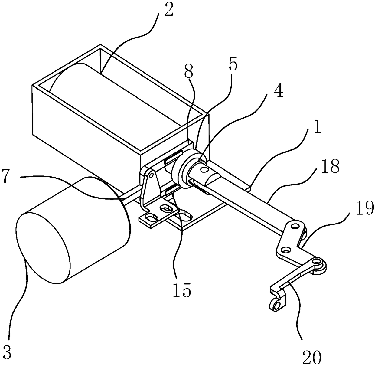
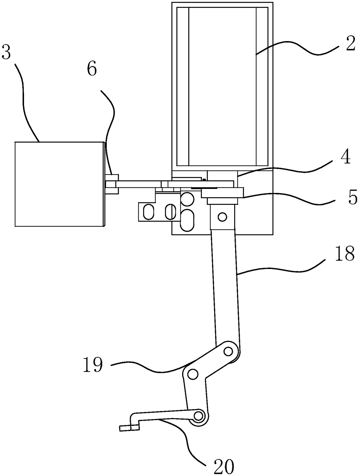
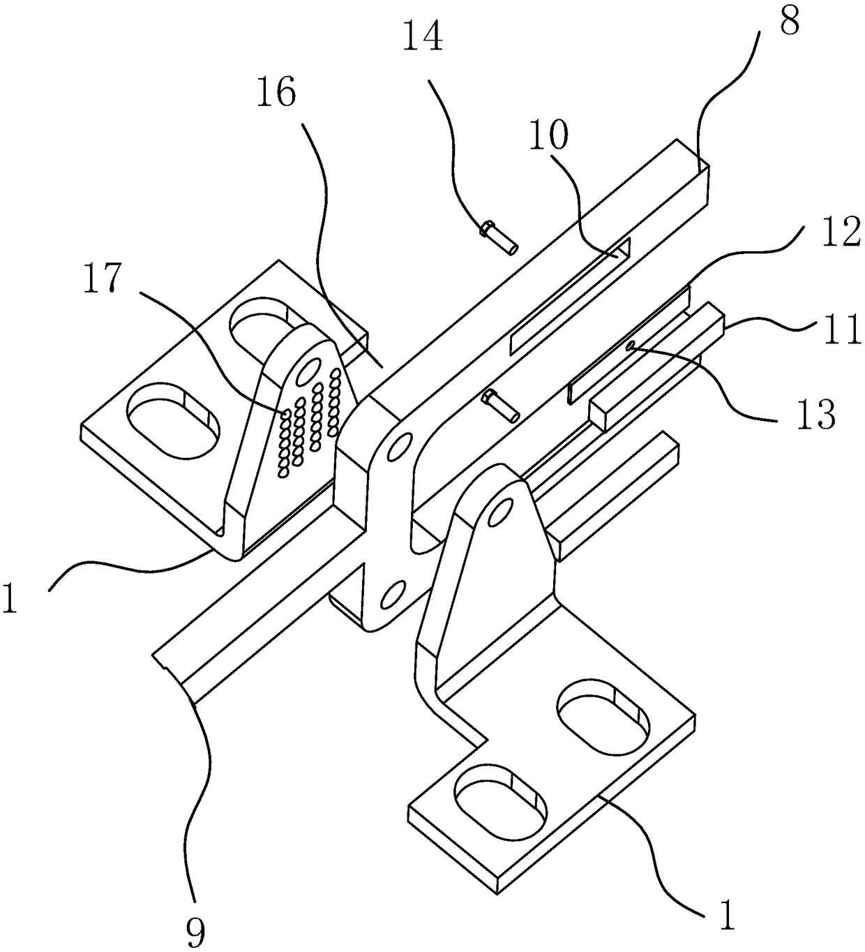
[0023] Such as figure 1 , figure 2 , image 3 As shown, the sewing machine includes a base 1, the base 1 is provided with a reverse stitching drive source 2 and a tight sewing drive source 3, the reverse stitching drive source 2 is provided with a reverse stitching output shaft 4, and the end of the reverse stitching output shaft 4 passes through The connecting rod mechanism is connected with the backstitch swing seat of the sewing machine, and the backtitch output shaft 4 is also covered with a limit ring 5 and the two are fixedly matched; The seam output shaft 6, the end of the tight seam output shaft 6 is provided with a limit fork 7, and two limit plates 8 are arranged at intervals on the limit fork 7, and the close...


PUM


Abstract

The invention belongs to the technical field of sewing devices, and relates to a sewing machine. The problem that an existing sewing machine is low in close joint stability is solved. The sewing machine comprises a base. A reverse joint driving source and a close joint driving source are arranged on the base. A reverse joint output shaft is movably arranged on the reverse joint driving source. Oneend of the reverse joint output shaft is connected with a reverse joint swing base of the sewing machine through a connecting rod mechanism. The reverse joint output shaft is sleeved with a limitingring and fixedly matched with the limiting ring. The close joint driving source is movably provided with a close joint output shaft perpendicular to the reverse joint output shaft. A limiting fork isarranged at one end of the close joint output shaft and provided with two limiting plates at intervals. The close joint driving source can drive the limiting fork to move through the close joint output shaft so that a limiting plate on the limiting fork can abut against the upper end and the lower end of the limiting ring. The sewing machine has the advantage of being good in close joint stability.

Description

technical field [0001] The invention belongs to the technical field of sewing equipment, and relates to a sewing machine. Background technique [0002] As we all know, when trimming the thread of the lockstitch sewing machine, because the stitch length cannot be adjusted, the bottom thread end of a stitch length cannot form self-locking, and two thread ends, one long and one short, appear at the trimming place of the sewing material, and the two thread ends are aligned. Long and short, one front and one back, the thread ends left after thread trimming are not firm, and will fall off with a slight pull, affecting the sewing effect. In addition, the end of the thread is too long, which affects the aesthetic feeling. Therefore, in order to solve the above problems in the prior art, the sealing function is usually used, that is, the sealing electromagnet is used to energize, and then the corresponding components are driven to realize the movement of the swing seat to a very sma...

Claims


Application Information

Patent Timeline
Patent Type & Authority Applications(China)
IPC IPC(8): D05B69/18D05B69/32
CPCD05B69/18D05B69/32
Inventor 石学智杨淑洁
Owner ZHEJIANG OCEAN UNIV
Learn More