
A pipe column foundation structure for rapid turnover construction and its application method

A pipe column foundation and fast technology, which is applied in the direction of basic structure engineering, construction, bridge construction, etc., can solve the problems of inability to achieve rapid turnover and rapid construction, reduce the safety performance of the pipe column foundation structure, and affect the force effect of the steel pipe column, etc. , to achieve the effect of saving erection efficiency, saving labor time, and reducing the workload of on-site workers

Active Publication Date: 2020-12-01
THE 2ND ENG CO LTD MBEC +1
View PDF1 Cites 0 Cited by
  • Summary
  • Abstract
  • Description
  • Claims
  • Application Information

AI Technical Summary

Problems solved by technology

The support columns of the beam support are mostly set on both sides of the cap, and the foundation is expanded by using the embedded parts of the cap or cast-in-situ concrete. Among them, the embedded parts and the enlarged foundation are mostly invested at one time, and it is difficult to turn over and utilize them.
In the existing technology, the foundation structure of the pipe column is connected by embedded parts, and the steel pipe column is welded to the embedded parts, which cannot achieve fast turnover and rapid construction. The steel pipe column welded on it is uneven, which affects the actual stress effect of the steel pipe column
When the steel pipe column on the cap side falls on the outside of the cap, the foundation needs to be expanded, and if the installation of the steel pipe column on the cap is inconsistent with the steel pipe column falling on the outside of the cap, the settlement difference is obvious, which reduces the safety performance of the pipe column foundation structure

Method used


Image

  • A pipe column foundation structure for rapid turnover construction and its application method
  • A pipe column foundation structure for rapid turnover construction and its application method
  • A pipe column foundation structure for rapid turnover construction and its application method

Examples


Embodiment

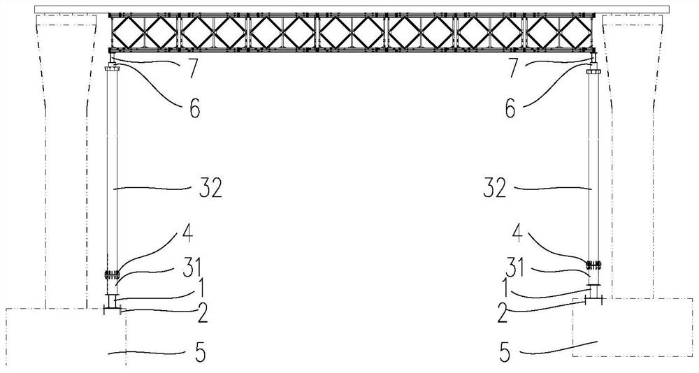
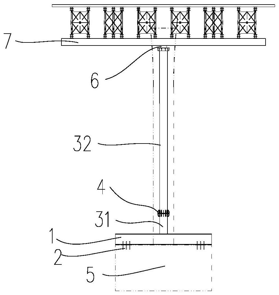
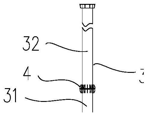
[0049] see Figure 1~3 As shown, the embodiment of the present invention provides a pipe column foundation structure for rapid turnover construction, including a bottom distribution beam 1, a group of steel pipe column assemblies 3 and a top distribution beam 7; It can be detachably installed on the bearing platform 5; each set of the steel pipe column assembly 3 includes a flanged steel pipe column 32 and a steel pipe column foot 31, wherein the steel pipe column foot 31 is welded to the bottom distribution beam 1, The upper end of the steel pipe column foot 31 is flange-connected with a steel pipe column 32 ;

[0050] The installation and connection in the pipe string foundation structure mostly adopts a detachable connection structure, which realizes the rapid installation and disassembly of the pipe string foundation structure, which is convenient for rapid construction and use. Of course, the method of using the pipe column foundation structure is simple, which saves the...


PUM


Abstract

The invention discloses a pipe column foundation structure for fast circulating construction. A bottom allocation beam, at least one set of steel pipe column assembly and a top allocation beam are included; the bottom allocation beam is used for being detachably installed on a bearing table; each set of steel pipe column assembly comprises a steel pipe column and a steel pipe column foot which aredetachably connected with each other; the steel pipe column feet are connected to the bottom allocation beam; the upper ends of the steel pipe column feet are all detachably connected with the steelpipe columns; and the top allocation beam is detachably erected on the steel pipe columns. The invention further discloses a construction method of the pipe column foundation structure. The pipe column foundation structure is safe and reliable and capable of being fast constructed and repeatedly circulated for use, the pipe column foundation structure erecting efficiency is improved, and the totalcost of cast-in-place beam construction is lowered.

Description

technical field [0001] The invention relates to the technical field of bridge construction, in particular to a pipe string foundation structure for rapid turnover construction and a use method. Background technique [0002] In the construction of small and medium-span concrete cast-in-place beams, the beam support has better safety and economy than the full hall support. The support columns of the beam support are mostly set on both sides of the cap, and the foundation is enlarged by using the embedded parts of the cap or cast-in-situ concrete. Among them, the embedded parts and the enlarged foundation are mostly one-time investment, and it is difficult to turn them around. In the existing technology, the pipe column foundation structure is connected by embedded parts, and the steel pipe column is welded to the embedded parts, which cannot achieve fast turnover and rapid construction. The steel pipe column welded on it is uneven, which affects the actual stress effect of th...

Claims


Application Information

Patent Timeline
Patent Type & Authority Patents(China)
IPC IPC(8): E02D27/42E01D21/00
CPCE01D21/00E02D27/42
Inventor 张洋张金杯陈亚强王晓敬王慧娟程文博
Owner THE 2ND ENG CO LTD MBEC
Learn More