Connecting structure of gas stove burner and spraying nozzle

A connection structure and gas stove technology, applied in the field of gas stoves, can solve the problems that gas cannot enter straightly, reduce the combustion performance of gas stoves, and affect the intake air of the burner, so as to facilitate manufacturing, improve combustion performance, and ensure normal air intake Effect

Pending Publication Date: 2019-02-01
宁波爷玛喜电器有限公司
View PDF0 Cites 0 Cited by
  • Summary
  • Abstract
  • Description
  • Claims
  • Application Information

AI Technical Summary

Problems solved by technology

But above-mentioned structure also has the following deficiencies in actual application: we know, nozzle generally all has nozzle hole and gas passage, because the aperture of nozzle hole is far smaller than the aperture of gas passage, so when gas enters gas passage from nozzle hole In the middle, the gas has a diffusion process. Although the gas channel can guide the gas, but because the gas channel is short and the flow rate of the gas is fast, when the gas flows out from the outlet end of the gas channel, it enters the burner. When the gas is injected into the tube, the gas will still spread rapidly to the surroundings while it continues to flow forward, and the inlet end of the injection tube of the burner is in the shape of a bell mouth, which provides a diffusion space for the gas, so not only will some gas It cannot enter the injection tube of the burner head straightly, and the diffused gas is easy to form turbulent flow at the inlet end of the injection tube of the burner head, which will affect the intake air of the burner head and greatly reduce the combustion performance of the gas stove

Method used


Image

  • Connecting structure of gas stove burner and spraying nozzle
  • Connecting structure of gas stove burner and spraying nozzle
  • Connecting structure of gas stove burner and spraying nozzle

Examples


Embodiment 2

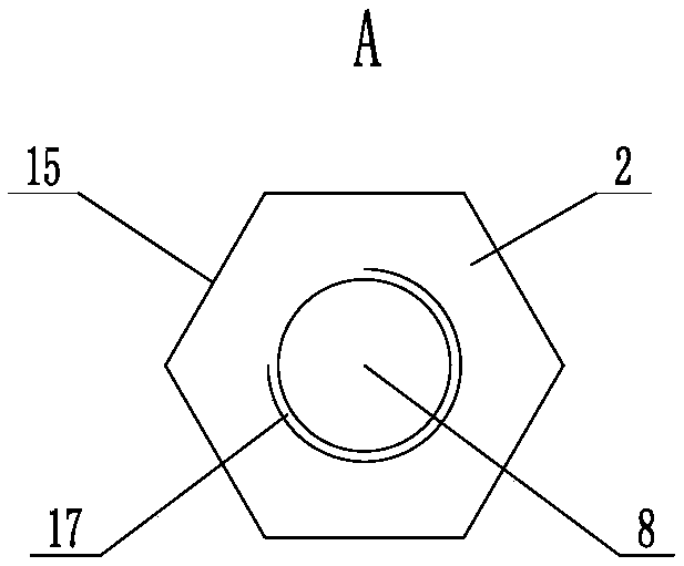
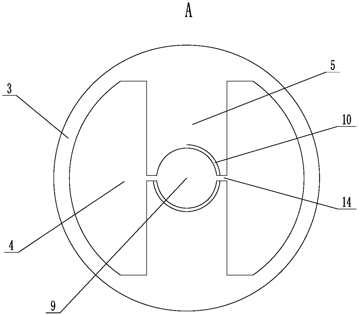
[0051] The difference between this embodiment and Embodiment 1 is that the connection structure between the guide tube 2 and the fixed plate 5 is different, such as Figure 4 and Figure 5 As shown, in this embodiment, the dividing gap 14 and the fixing hole 9 are not provided on the fixing plate 5, and the guide tube 2 and the fixing plate 5 are integrated, that is, the guide tube 2 and the fixing plate 5 are integrally formed. This structure makes the guide tube 2 No separate manufacturing is required, and there is no need to use other structures for connection and fixing between the guide pipe 2 and the fixing plate 5, which greatly facilitates the manufacture and assembly of the gas stove. At this time, there is no need to open a fixing hole 9 on the fixing plate 5 , but the guide through hole 8 needs to extend to the fixing plate 5 and pass through it.

[0052] Since the guide tube 2 and the fixed plate 5 are integrated, there is no need to set the limit step 13 and the ...

Embodiment 3

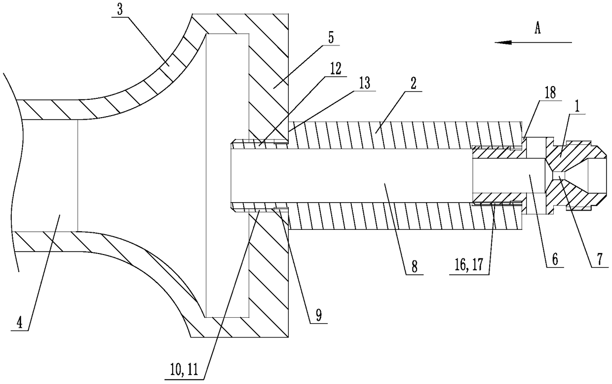
[0054] The difference between this embodiment and embodiment 1 is that the connection structure between the guide pipe 2 and the nozzle 1 is different, such as Figure 6 As shown, in the present embodiment, one end of the nozzle 1 stretches into the guide tube 2 from the air inlet of the guide through hole 8, and cooperates with the inner wall clearance of the guide through hole 8, that is, the end of the nozzle 1 air outlet. The outer peripheral wall is smooth and cylindrical, and the second external thread 16 is no longer provided, so that after one end of the air outlet of the nozzle 1 is inserted into the guide tube 2, the outer peripheral wall is adjacent to or close to the inner wall of the guide through hole 8 .

[0055] Further, the outer peripheral wall of the middle part of the nozzle 1 can be provided with a limiting boss 18, and one end of the limiting boss 18 is pressed against one end of the guide pipe 2. In this embodiment, the limiting boss 18 is directed towar...

Embodiment 4

[0058] The difference between this embodiment and embodiment 2 is that the connection structure between the guide pipe 2 and the nozzle 1 is different, such as Figure 6 As shown, in the present embodiment, one end of the nozzle 1 stretches into the guide tube 2 from the air inlet of the guide through hole 8, and cooperates with the inner wall clearance of the guide through hole 8, that is, the end of the nozzle 1 air outlet. The outer peripheral wall is smooth and cylindrical, and the second external thread 16 is no longer provided, so that after one end of the air outlet of the nozzle 1 is inserted into the guide tube 2, the outer peripheral wall is adjacent to or close to the inner wall of the guide through hole 8 .

[0059] Further, the outer peripheral wall of the middle part of the nozzle 1 can be provided with a limiting boss 18, and one end of the limiting boss 18 is pressed against one end of the guide pipe 2. In this embodiment, the limiting boss 18 is directed towar...


PUM

PropertyMeasurementUnit
Lengthaaaaaaaaaa

Abstract

The invention relates to a connecting structure of a gas stove burner and a spraying nozzle. The connecting structure comprises a burner, a spraying nozzle and a guide pipe. The burner comprises an injection pipe which is provided with a gas input channel. A fixing plate is arranged on the portion, located at a gas inlet of the gas input channel, of the injection pipe. The spraying nozzle is provided with a fuel gas channel and a spraying hole. The guide pipe is provided with a guide through hole. One end of the guide pipe is connected to the fixing plate. A gas outlet of the guide through hole communicates with the gas inlet of the gas input channel. The guide through hole and the gas input channel are formed coaxially. The other end of the guide pipe and one end of the spraying nozzle are connected. The gas inlet of the guide through hole communicates with a gas outlet of the spraying nozzle. The guide through hole and the spraying hole are arranged coaxially. The connecting structure has the advantages that fuel gas can enter the injection pipe of the burner straightly, the situation that the fuel gas forms turbulent flow at the inlet end of the injection pipe of the burner canbe avoided, thus normal gas input of the burner is effectively ensured, and the combustion performance of a gas stove is improved.

Description

technical field [0001] The invention relates to a gas stove, in particular to a connection structure between a burner head and a nozzle of a gas stove. Background technique [0002] Traditional gas-cooker all has burner and nozzle, and one end of nozzle is connected at the ejection pipe inlet end of burner, and then is provided with damper regulating mechanism between burner and nozzle. At present, some gas stoves set the adjustment mechanism of the primary air intake volume on the bottom shell or the stove panel, so as to save the damper adjustment mechanism between the burner head and the nozzle, so that the nozzle can be directly connected to the burner head. , thereby reducing the shaking of the nozzle and effectively improving the stability of the gas intake. But above-mentioned structure also has the following deficiencies in actual application: we know, nozzle generally all has nozzle hole and gas passage, because the aperture of nozzle hole is far smaller than the a...

Claims


Application Information

Patent Timeline
IPC IPC(8): F23D14/02F23D14/46F23D14/64F24C3/08
CPCF23D14/02F23D14/46F23D14/64F24C3/085
Inventor 胡国定
Owner 宁波爷玛喜电器有限公司
Why Eureka
Try Eureka