Pantograph and pantograph head assembly

A bow head and component technology, applied in the field of pantograph and bow head components, can solve problems such as poor contact, affecting the normal charging of electric vehicles, and failure

Pending Publication Date: 2021-05-14
XJ ELECTRIC +2
View PDF0 Cites 0 Cited by
  • Summary
  • Abstract
  • Description
  • Claims
  • Application Information

AI Technical Summary

Problems solved by technology

[0005] The purpose of the present invention is to provide a bow head assembly to solve the technical problem in the prior art that the relative horizontal plane is prone to deflection in the direction of the length of the conductive plate during the upward movement of the conductive plate, resulting in poor contact between the bow head assembly and the power supply electrode plate The corresponding object of the present invention is also to provide a pantograph to solve the technical problem in the prior art that the bow head assembly and the power supply plate are easy to conduct poor contact and affect the normal charging of the electric vehicle

Method used


Image

  • Pantograph and pantograph head assembly
  • Pantograph and pantograph head assembly
  • Pantograph and pantograph head assembly

Examples


specific Embodiment 1

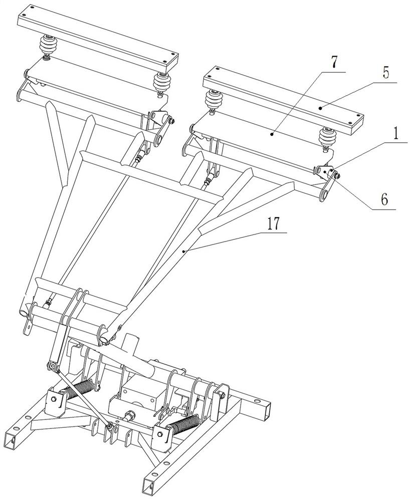
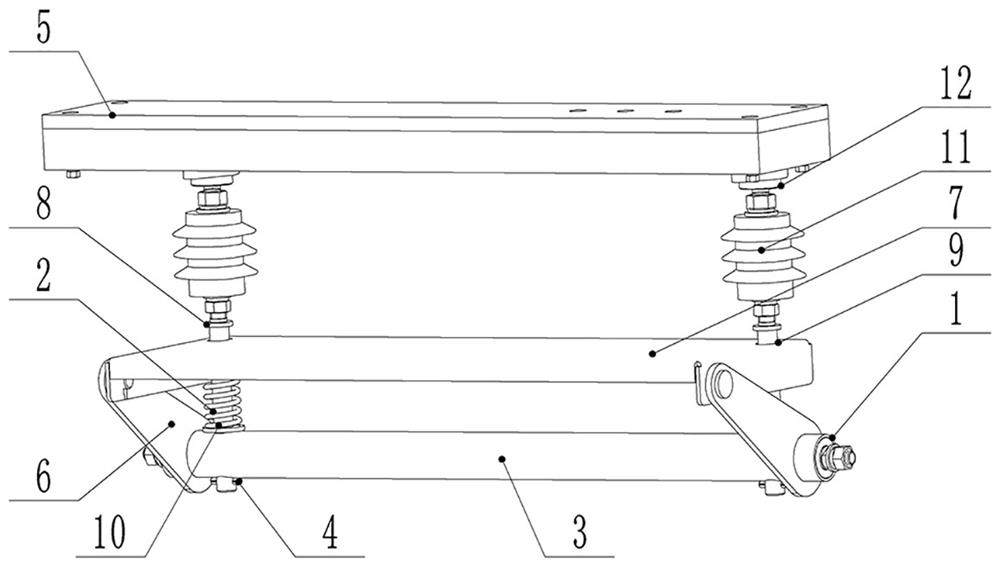
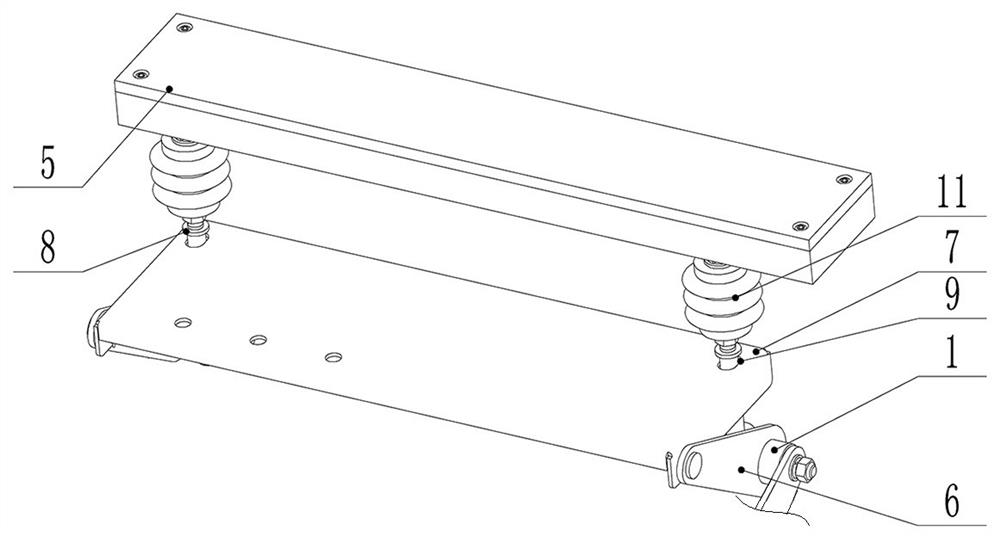
[0032] Such as figure 1 and figure 2 As shown, the bow head assembly includes a bow head support 1 and a support rod 2 guided and assembled on the bow head support 1. The bow head support 1 includes a rotating shaft 3 for transmission connection with the drive mechanism 17 of the pantograph. The rotating shaft 3 is provided with There are two through holes arranged at intervals along its length direction, the through holes on the rotating shaft 3 are radial through holes, two support rods 2 are provided, and pass through corresponding through holes along the up and down direction, the One end of the plate is provided with a pin shaft 4, and the pin shaft 4 is engaged with the rotating shaft 3 so as to restrict the support rod 2 from passing through the through hole from the upper side.

[0033] Such as figure 2 As shown, the upper end of the support rod 2 is fixedly connected with the conductive plate 5 so that the conductive plate 5 can guide and move relative to the bow ...

specific Embodiment 2

[0040] The difference from Embodiment 1 is that the bow bracket can also include a bent plate, the bent plate is formed by a horizontal plate and a vertical plate, the horizontal plate is provided with a through hole, the support rod is guided and assembled in the through hole, and the balance plate is hinged On the vertical plate, and the hinge axis extends along the length direction of the conductive plate; or a straight plate can be included between the bow heads, there is a through hole above the straight plate, the support rod is assembled in the through hole, and the balance pressure plate is hinged on the The edge of the straight plate is away from the through hole, and the hinge axis extends along the length direction of the conductive plate.

specific Embodiment 3

[0042] It differs from Embodiment 1 in that three or four crank arms on the rotating shaft can be arranged at intervals along the length direction of the rotating shaft; or when the size of the crank arm along the length direction of the rotating shaft is large, the crank arm One arm can also be provided, and the crank arm is arranged at the middle position in the length direction of the rotating shaft. The specific number and location of the crank arms can be selected arbitrarily according to the actual situation, as long as the structural stability of the connection between the rotating shaft and the balance plate can be satisfied, and the rotating shaft does not affect the guiding movement of the support rod in the up and down direction.


PUM


Abstract

The invention relates to a pantograph and a pantograph head assembly. The pantograph head assembly comprises a pantograph head support, a long-strip-shaped current-conducting plate and a supporting rod for supporting the current-conducting plate, and the supporting rod is assembled on the pantograph head support in a guiding mode. A balance pressing plate is hinged to the pantograph head support, the supporting rod is sleeved with a spring for pressing the balance pressing plate on the supporting rod, the balance pressing plate is provided with a penetrating hole or a penetrating groove for the supporting rod to penetrate through, the penetrating hole or the penetrating groove extends in the width direction of the current-conducting plate, the penetrating hole or the penetrating groove is provided with two hole side walls or groove side walls in sliding fit with the supporting rod, and the supporting rod can be limited to swing in the length direction of the current-conducting plate. The pantograph head assembly of the structure can increase the guide distance of the supporting rod moving in the vertical direction, improve the stability of the current-conducting plate in the vertical moving process, reduce the possibility that the current-conducting plate swings in the length direction in the upward moving process to cause poor contact between the current-conducting plate and a power supply polar plate, and ensure the normal charging operation of an electric vehicle.

Description

technical field [0001] The invention relates to a pantograph and a bow head assembly. Background technique [0002] The pantograph is a current receiving device for electric vehicles to receive current from the power supply plate of the charging bow. The pantograph includes a chassis, a bow assembly, and a drive mechanism that drives the bow assembly up and down. The drive mechanism is installed on the chassis. When the electric vehicle is charged, the drive mechanism drives the bow assembly to rise, and the bow assembly contacts the power supply plate. Take the current to charge the electric vehicle. [0003] In the prior art, the bow head assembly includes a rotating shaft connected to the drive mechanism and a conductive plate in conductive contact with the power supply plate. The conductive plate is in the shape of a long strip, and the conductive plate is guided by two support rods arranged at intervals in its length direction. Assembled on the rotating shaft, the sup...

Claims


Application Information

Patent Timeline
IPC IPC(8): B60L53/14B60L5/28
CPCB60L53/14B60L5/28Y02T10/70Y02T10/7072Y02T90/14
Inventor 魏伟方春阳周亚龙穆贝贝王庭奇宋兴华李哲胡占伟
Owner XJ ELECTRIC
Why Eureka
Try Eureka