Main deck pile fixing frame of non-self-propelled self-elevating wind power installation platform

A technology for installing platforms and fixing pile frames, applied in sheet pile walls, water conservancy projects, artificial islands, etc., can solve the problems of increased friction, time-consuming and laborious, adverse effects of platforms, etc., to ensure the guiding distance, increase the guiding distance, The effect of saving labor costs

Pending Publication Date: 2020-07-31
南通长青沙船舶工程有限公司
View PDF0 Cites 0 Cited by
  • Summary
  • Abstract
  • Description
  • Claims
  • Application Information

AI Technical Summary

Problems solved by technology

[0003] However, there are still some defects in the existing platform pile-fixing frame. When the guide ring beam inside the main body of the pile-fixing frame moves up and down for a long time during use, the friction force will increase, which reduces the efficiency of guiding the ring beam to move up and down, and cannot guide the ring beam. The guide distance of the pile legs, and thus have adverse effects on the platform during the towing process, and the installation and disassembly process between the third connecting plate, the first connecting plate and the second connecting plate on the device is cumbersome, time-consuming and laborious. The installation and disassembly efficiency of the device is reduced, and the structural strength of the device cannot be guaranteed. Therefore, we propose a non-self-propelled self-elevating wind power installation platform main deck pile fixing frame

Method used


Image

  • Main deck pile fixing frame of non-self-propelled self-elevating wind power installation platform
  • Main deck pile fixing frame of non-self-propelled self-elevating wind power installation platform
  • Main deck pile fixing frame of non-self-propelled self-elevating wind power installation platform

Examples


Embodiment Construction

[0022] The following will clearly and completely describe the technical solutions in the embodiments of the present invention with reference to the accompanying drawings in the embodiments of the present invention. Obviously, the described embodiments are only some, not all, embodiments of the present invention. Based on the embodiments of the present invention, all other embodiments obtained by persons of ordinary skill in the art without making creative efforts belong to the protection scope of the present invention.

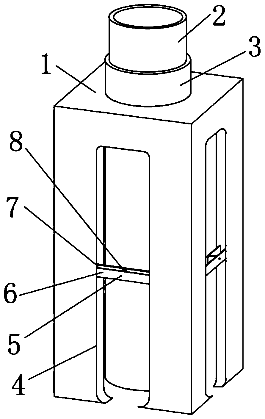
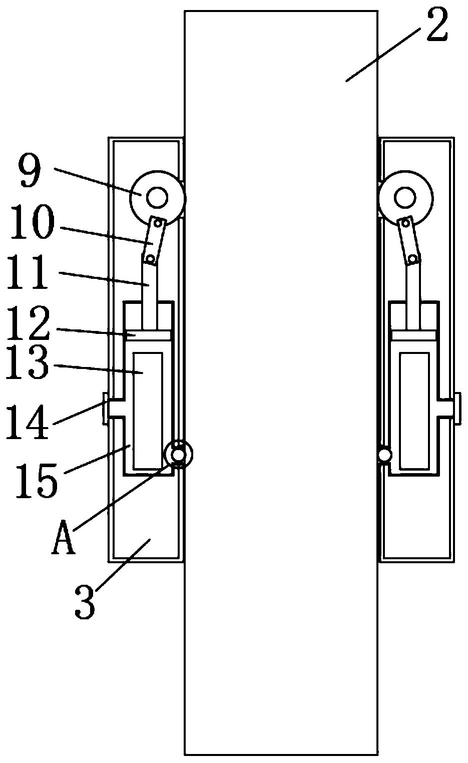
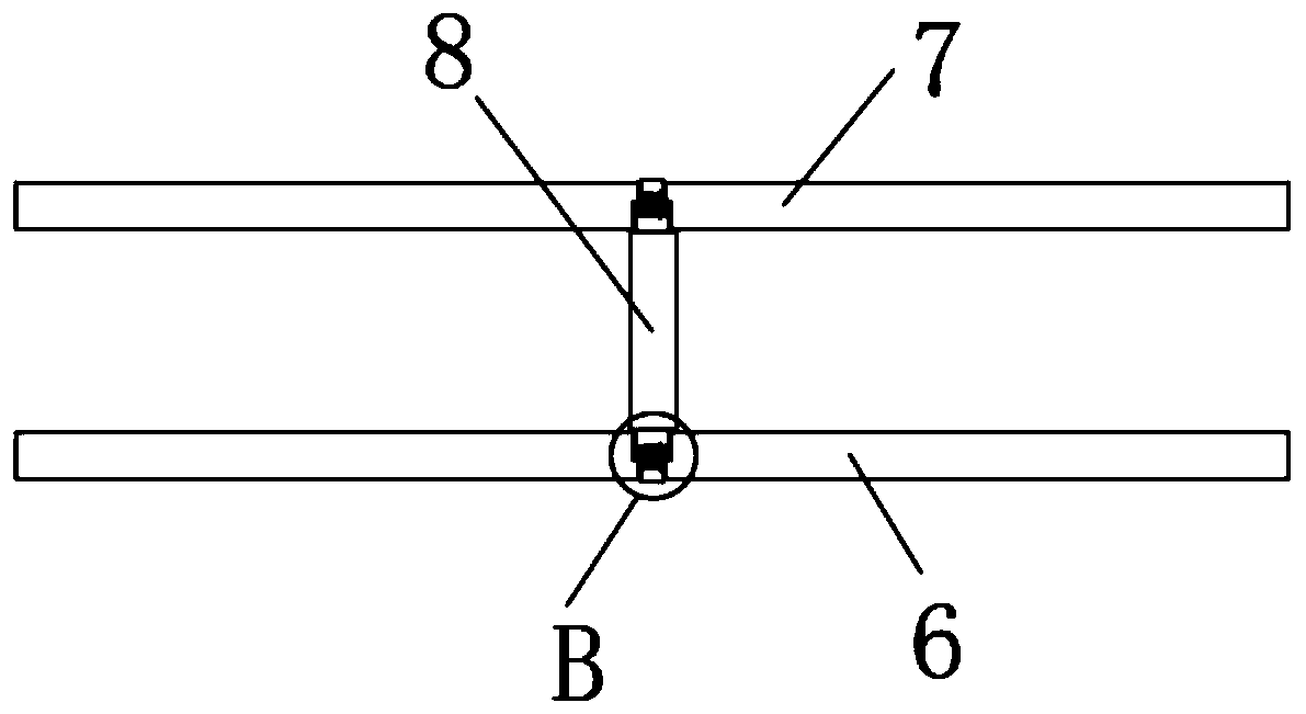
[0023] see Figure 1-5 , the present invention provides a technical solution: a non-self-propelled self-elevating wind power installation platform main deck pile fixing frame, including a pile fixing frame main body 1, a guide ring beam 2, a lubrication mechanism and a convenient mechanism, and the lubrication mechanism is located at the pile fixing frame main body 1 At the gap with the guide ring beam 2, the lubricating mechanism includes a sleeve 3, the insi...


PUM


Abstract

The invention discloses a main deck pile fixing frame of a non-self-propelled self-elevating wind power installation platform. The main deck pile fixing frame comprises a pile fixing frame body, a guide ring beam, a lubricating mechanism and a convenient mechanism, wherein the lubricating mechanism is located at the gap between the pile fixing frame body and the guide ring beam; and the lubricating mechanism comprises a sleeve. According to the main deck pile fixing frame, through the arrangement of the sleeve, the situation that the guide ring beam in the pile fixing frame body moves up and down for a long time, and the friction force is increased is effectively avoided, the guide ring beam is lubricated, the up-down moving efficiency of the guide ring beam is effectively improved, then the guide distance of the guide ring beam to pile legs is guaranteed, and the platform is safer and more reliable in the towing process; and through the arrangement of clamping blocks, the situation that the mounting and dismounting processes between a third connecting plate and a first connecting plate and between the third connecting plate and a second connecting plate are tedious is effectivelyavoided, the labor cost is saved advantageously, the mounting and dismounting efficiency of the device is improved, meanwhile, the structural strength of the device is guaranteed, and the main deck pile fixing frame can also be used as an oil cylinder mounting seat.

Description

technical field [0001] The invention belongs to the technical field of offshore platforms, and in particular relates to a non-self-propelled self-elevating wind power installation platform main deck pile fixing frame. Background technique [0002] With the vigorous development of China's wind farms, it is possible to install wind turbine components, wind farm operation and maintenance operations, and various large-scale equipment on the shore in offshore wind farms. Marine engineering equipment for hoisting tasks or live support. It can operate as a jack-up platform in muddy sandy seabed sea areas or similar sea areas within the maximum water depth of 50m. The platform is equipped with 4 cylindrical legs, and the supporting legs need to use the pile frame. [0003] However, there are still some defects in the existing platform pile-fixing frame. When the guide ring beam inside the main body of the pile-fixing frame moves up and down for a long time during use, the friction...

Claims


Application Information

Patent Timeline
Patent Type & Authority Applications(China)
IPC IPC(8): E02D13/00E02D13/04E02B17/08
CPCE02B17/08E02D13/00E02D13/04
Inventor 邱磊包勇飞薛家鑫柏小明蒲方刚
Owner 南通长青沙船舶工程有限公司
Why Eureka
Try Eureka