Spiral water pipe electric heating device of water heater
An electric heating device and water heater technology, which is applied to water heaters, fluid heaters, lighting and heating equipment, etc., can solve the problems of short water circuit, no further improvement of heating efficiency, and influence on heating efficiency, and achieve the effect of fast heating speed.
- Summary
- Abstract
- Description
- Claims
- Application Information
AI Technical Summary
Problems solved by technology
Method used
Image

Examples
Embodiment 1
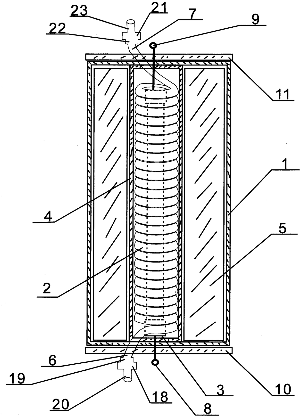
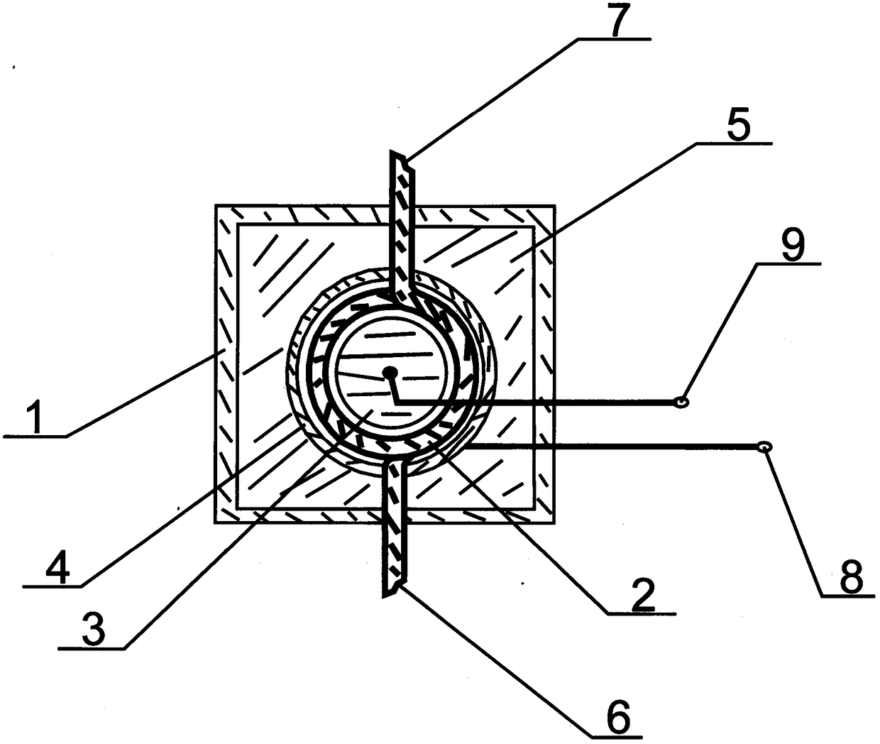
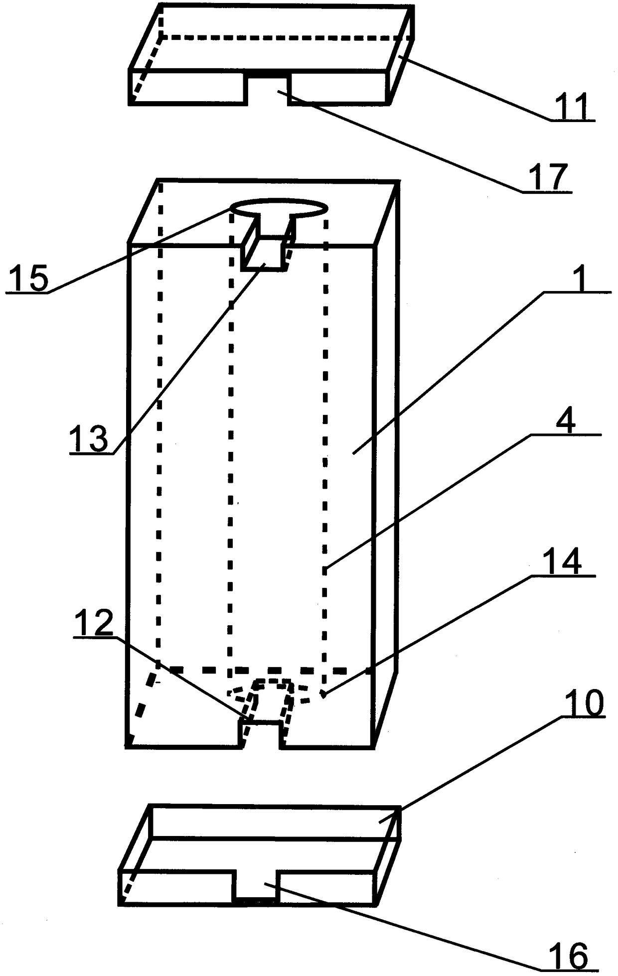
[0029] Embodiment 1: as attached figure 1 , 2, 3, the upper and lower ends of the heating box 1 are respectively provided with a round hole, a heat reflection tube 4 passes through the round hole, and the two ends of the heat reflection tube 4 are fixed in the round holes at the upper and lower ends of the heating box 1 position, a spiral water pipe 2 is set into the pipe of the heat reflection pipe 4, and a heating pipe 3 is set into the spiral pipe of the spiral water pipe 2; a heat reflection pipe 4, a spiral water pipe 2, and a heating pipe 3 are combined into a single pipe Combined heating system; the upper end of one surface of the heating box 1 has an upper channel opening 13 that communicates with an opening on the upper end of the heat reflection tube 4, allowing the outlet pipe 7 and the heating pipe 3 at one end of the spiral water pipe 2 The electric wire 9 at one end stretches out of the casing of the heating box 1, and the lower end of the heating box 1 has a lo...
Embodiment 2
[0031] Embodiment 2: as attached Figure 4 , 5 , 6, the difference between embodiment 2 and embodiment 1 is that the heating system of embodiment 2 adds a group of pipeline combinations to form a heating system with double pipeline combination, that is, the spiral water pipe 2 is set into the pipeline of the heat reflection tube 4 , the heating pipe 3 is set into the spiral pipe of the spiral water pipe 2 to form a group of pipe combinations, the spiral water pipe 2a is set into the pipe of the heat reflection pipe 4a, and the heating pipe 3a is set into the spiral pipe of the spiral water pipe 2a to form another group Pipeline combination, two sets of pipelines are combined into a heating system with double pipeline combination, the water inlet pipes 6, 6a at one end of the two spiral water pipes 2, 2a of the heating system are respectively connected to the water outlets 19, 19a of the water inlet pipe connecting piece 18, and the water inlet pipes 20 connects the tap water ...
Embodiment 3
[0033] Embodiment 3: as attached Figure 7 , 8 As shown, embodiment 3 has the same points as embodiment 2, that is, the spiral water pipes 2, 2a are respectively set into the pipes of the heat reflection pipes 4, 4a, and the heating pipes 3, 3a are respectively set into the spiral pipes of the spiral water pipes 2, 2a , forming a heating system composed of two groups of pipelines; the upper and lower ends of the heating box 1 are respectively provided with two round holes, the heat reflection tubes 4, 4a pass through the round holes respectively, and the two ends of the heat reflection tubes 4, 4a are respectively fixed on the heating There are two corresponding round hole positions at the upper and lower ends of the box 1; embodiment 3 has the same structure as the heating box 1 of embodiment 2, and the heating box 1 has an upper cover 11 to cover the upper end of the heating box 1, and the heating box 1 There is a lower cover 10 to cover the lower end of the heating box 1; ...
PUM
 Abstract
Description
Claims
Application Information
 - Generate Ideas
- Intellectual Property
- Life Sciences
- Materials
- Tech Scout
- Unparalleled Data Quality
- Higher Quality Content
- 60% Fewer Hallucinations
Browse by: Latest US Patents, China's latest patents, Technical Efficacy Thesaurus, Application Domain, Technology Topic, Popular Technical Reports.
© 2025 PatSnap. All rights reserved.Legal|Privacy policy|Modern Slavery Act Transparency Statement|Sitemap|About US| Contact US: help@patsnap.com