
illuminated keyboard

A technology of luminous keyboards and luminous components, which is applied in the direction of electrical components, legends, electric switches, etc., and can solve the problems of inability to achieve uniform light effects, concentrated light projection effects, and inability to achieve

Active Publication Date: 2020-10-16
PRIMAX ELECTRONICS LTD
View PDF5 Cites 0 Cited by
  • Summary
  • Abstract
  • Description
  • Claims
  • Application Information

AI Technical Summary

Problems solved by technology

[0008] In recent years, users hope to be able to control the luminous effect of each button in the luminous keyboard, for example: control button A to emit light, but button B does not emit light, but the above-mentioned existing luminous keyboard 2 cannot meet the above-mentioned requirements
In order to meet the needs of users, a direct-type light-emitting keyboard must be used, and a direct-type light-emitting keyboard is to install a single direct-type light-emitting diode under the key cap of each button, and each direct-type light-emitting diode can be controlled separately. The light-emitting situation of the polar body is to meet the needs of users. Among them, the light beam generated by the direct-type light-emitting diode is directly projected upward to the corresponding key cap, so the light projection effect of the direct-type light-emitting keyboard is too concentrated, and the Unable to achieve light uniformity

Method used


Image

  • illuminated keyboard
  • illuminated keyboard
  • illuminated keyboard

Examples


Embodiment Construction

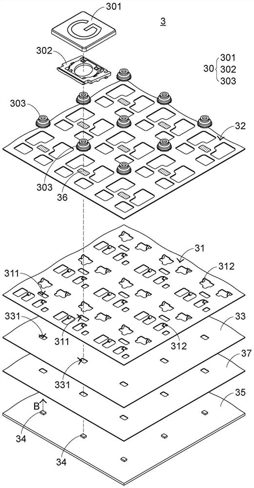
[0042] In view of the problems of the prior art, the present invention provides a keyboard which can solve the problems of the prior art. First illustrate the structure of the luminous keyboard of the present invention, please refer to image 3, which is an exploded schematic diagram of a partial structure of the light-emitting keyboard in the first preferred embodiment of the present invention. The luminous keyboard 3 of the present invention includes a plurality of keys 30 (only one is shown in the figure), a support plate 31, a switch circuit board 32, a light guide plate 33, a plurality of direct-type light-emitting elements 34, a power supply circuit board 35, a first reflective element 36 and The second reflective element 37 , and each direct light emitting element 34 corresponds to a key 30 . A plurality of keys 30 are exposed outside the luminous keyboard 3, and a support plate 31 is located below the plurality of keys and connected to the plurality of keys 30. The su...


PUM


Abstract

The invention discloses a light-emitting keyboard, which comprises a key, a support plate with an opening, a switch circuit board, a light guide plate, a straight-down light-emitting element capable of generating a light beam and a reflection element, wherein the support plate is located below the key; the switch circuit board is arranged on the support plate; the light guide plate is located below the support plate and is provided with a light guide plate hole; the straight-down light-emitting element extends to the light guide plate hole; and the reflection element is located between the straight-down light-emitting element and the key. When a light beam passes through the opening, the light beam passes through the switch circuit board, is reflected by the reflection element and enters the light guide plate, and the light guide plate guides the light beam to be projected to the peripheral area of the key.

Description

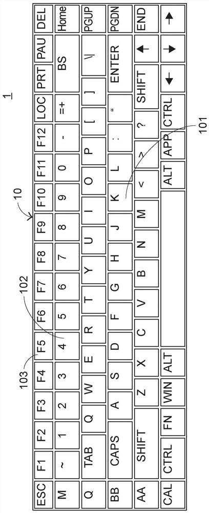
technical field [0001] The invention relates to a keyboard, in particular to a luminous keyboard capable of producing luminous effects. Background technique [0002] Common computer peripheral input devices include a mouse, a keyboard, and a trackball. The keyboard can directly input text and symbols to the computer, so it is highly valued by users and input device manufacturers. [0003] see figure 1 , which is a schematic diagram of an appearance structure of an existing keyboard. A plurality of keys 10 are exposed on the surface of the existing keyboard 1, and the plurality of keys 10 are classified into general keys 101, number keys 102, and function keys 103, etc., and the plurality of keys are generated by pressing the user's fingers. Corresponding signals are given to the computer, so that the computer performs the pressed button function. For example, the general key 101 is used to input symbols such as English letters, the numeric key 102 is used to input numbers,...

Claims


Application Information

Patent Timeline
Patent Type & Authority Patents(China)
IPC IPC(8): H01H13/83
CPCH01H13/83H01H2219/06H01H2219/062
Inventor 蔡磊龙江英德
Owner PRIMAX ELECTRONICS LTD
Learn More