Luminous keyboard

A technology of luminous keyboards and luminous components, which is applied in the direction of legends, electrical components, electric switches, etc., and can solve the problem of uneven luminescence

Active Publication Date: 2019-01-18
PRIMAX ELECTRONICS LTD
View PDF4 Cites 1 Cited by
  • Summary
  • Abstract
  • Description
  • Claims
  • Application Information

AI Technical Summary

Problems solved by technology

However, the light beams generated by the direct-type light-emitting diodes are directly projected upwards onto the corresponding key caps, so the light projection effect of the direct-type light-emitting keyboard has the defect of being too concentrated, and symbols such as letters or numbers are scattered on the periphery of the key caps ( see figure 1 As far as the keys of the shown key cap 104) are concerned, this will make the luminous degree of each symbol 1041-1044 on the key cap uneven

Method used


Image

  • Luminous keyboard
  • Luminous keyboard
  • Luminous keyboard

Examples


Embodiment Construction

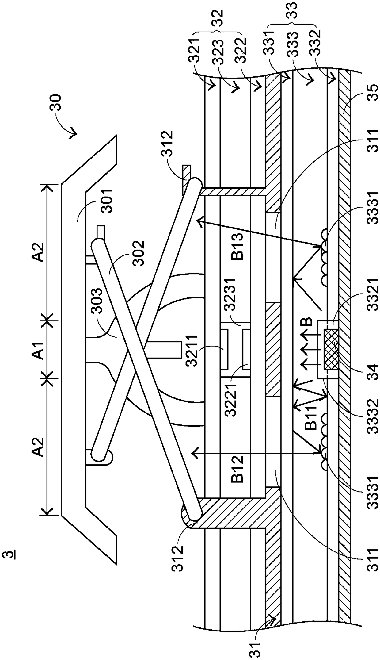
[0065] In view of the problems in the prior art, the present invention provides a light-emitting keyboard that can solve the problems in the prior art. First illustrate the structure of the luminous keyboard of the present invention, please refer to image 3 , which is a schematic cross-sectional view of a partial structure of the light-emitting keyboard in the first preferred embodiment of the present invention. The luminous keyboard 3 of the present invention includes a plurality of keys 30 (only one is shown in the figure), a support plate 31, a switch circuit board 32, a backlight module 33, a plurality of direct-type light-emitting elements 34 (only one is shown in the figure) and a power supply circuit board 35 , each direct light-emitting element 34 corresponds to a key 30 . And at least part of the structure of each button 30 is exposed outside the luminous keyboard 3 for the user to press, and the support plate 31 is located under the plurality of buttons 30, connect...


PUM


Abstract

A luminescent keyboard include keys, A support plate have openings in that support plate, A switch circuit board arranged on the support board, The backlight module comprises an upper reflective sheet, a lower reflective sheet and a light guide plate positioned between the upper reflective sheet and the lower reflective sheet, and the straight-down light emitting element extends into the light guide plate opening through the lower reflective sheet opening of the lower reflective sheet. A light beam output from a direct-down light emit element is transmitted to a light guide plate, and that light beam conduct in the light guide plate travels in the direction of the openings in the support plate through a plurality of microstructures in the light guide plate, and is project to keys after passing through the openings in the support plate and the switch circuit board.

Description

technical field [0001] The invention relates to the field of keyboards, in particular to a keyboard with a light-emitting function. Background technique [0002] Common computer peripheral input devices include a mouse, a keyboard, and a trackball. The keyboard can directly input text and symbols to the computer, so it is highly valued by users and input device manufacturers. [0003] see figure 1 , which is a schematic diagram of an appearance structure of an existing keyboard. A plurality of keys 10 are exposed on the surface of the existing keyboard 1, and the plurality of keys 10 are classified into general keys 101, number keys 102, and function keys 103, etc., and the plurality of keys are generated by pressing the user's fingers. Corresponding key signals are given to the computer, so that the computer performs the pressed key function. For example, the general key 101 is used to input characters and other symbols, the number key 102 is used to input numbers, and th...

Claims


Application Information

Patent Timeline
Patent Type & Authority Applications(China)
IPC IPC(8): H01H13/83
CPCH01H13/83H01H2219/036H01H2219/06H01H2219/062H01H2231/002
Inventor 陈仲渊
Owner PRIMAX ELECTRONICS LTD
Why Eureka
Try Eureka