
Antenna assembly and electronic device

A technology for antenna components and electronic equipment, applied in the electronic field, can solve problems such as high cost, achieve the effect of cost saving and wide coverage

Active Publication Date: 2019-02-01
GUANGDONG OPPO MOBILE TELECOMM CORP LTD
View PDF5 Cites 3 Cited by
  • Summary
  • Abstract
  • Description
  • Claims
  • Application Information

AI Technical Summary

Problems solved by technology

However, the first method requires rotation of the antenna array, requiring a large amount of space
The second method needs to add a large number of phase shifters, which is relatively expensive

Method used


Image

  • Antenna assembly and electronic device
  • Antenna assembly and electronic device
  • Antenna assembly and electronic device

Examples


Embodiment Construction

[0015] The following will clearly and completely describe the technical solutions of the embodiments of the present application with reference to the drawings in the embodiments of the present application.

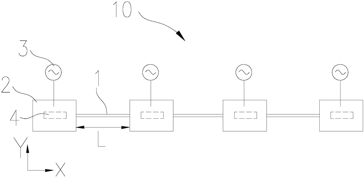
[0016] see figure 1 , figure 1 It is an antenna assembly 10 provided by the embodiment of this application. The antenna assembly 10 includes a guide 1 , a plurality of radiators 2 , a plurality of feed sources 3 and a driving mechanism 4 . The plurality of radiators 2 are slidably and spaced apart on the guide member 1 . There is a preset distance L between two adjacent radiators 2 . Each of the radiators 2 is electrically connected to at least one feed 3 , and the feed 3 is used to provide an excitation source for the radiator 2 so that the radiator 2 radiates antenna signals. The driving mechanism 4 connects the radiator 2 and the guide 1 . The driving mechanism 4 is used to drive the radiators 2 to slide along the guide 1 to change the preset distance L between two...


PUM


Abstract

The present invention provides an antenna assembly and an electronic device. The antenna assembly comprises a guiding component, a plurality of radiators, a plurality of feeding sources, and a drivingmechanism; the plurality of radiators are slidably disposed on the guiding component at intervals; each of the radiators is electrically connected to at least one of the feeding sources; the drivingmechanism is connected with the radiators and the guiding component; and the driving mechanism is used for driving the radiators to move along the guiding component, so that a distance between two adjacent radiators can be changed. The distances between the adjacent radiators are adjusted, so that the maximum radiation directions of the radiators can be adjusted, and therefore, the scanning of antenna beams can be realized, and the wide coverage of the high-gain antenna can be realized, and at the same time, the plurality of radiators slide on the guiding component, and do not occupy a largerthree-dimensional space; and a large number of phase shifters are not needed, and therefore, costs can be saved.

Description

technical field [0001] The present application relates to the field of electronic technology, in particular to an antenna assembly and electronic equipment. Background technique [0002] In the application of the array antenna, since the gain of the antenna is required to be high, the beam of the antenna is narrowed, and the coverage angle of a single beam of the antenna becomes smaller. To solve the problem of wide coverage of high-gain antennas, beam scanning is the most widely used technical method at present. There are currently two types of beam scanning, one is to achieve mechanical scanning of the antenna beam by rotating the antenna front, and the other is to provide different feed phases for different antenna elements to achieve electrical scanning of the antenna beam. However, the first method requires the rotation of the antenna array, which needs to provide a lot of space. The second method needs to add a large number of phase shifters, and the cost is relative...

Claims


Application Information

Patent Timeline
Patent Type & Authority Applications(China)
IPC IPC(8): H01Q1/50H01Q1/27H01Q1/22H01Q1/24H01Q3/26
CPCH01Q1/2258H01Q1/242H01Q1/273H01Q1/50H01Q3/26
Inventor 周林
Owner GUANGDONG OPPO MOBILE TELECOMM CORP LTD
Learn More