
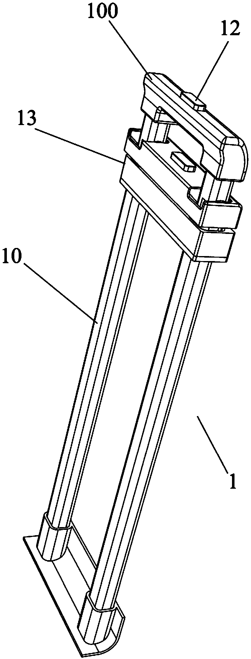
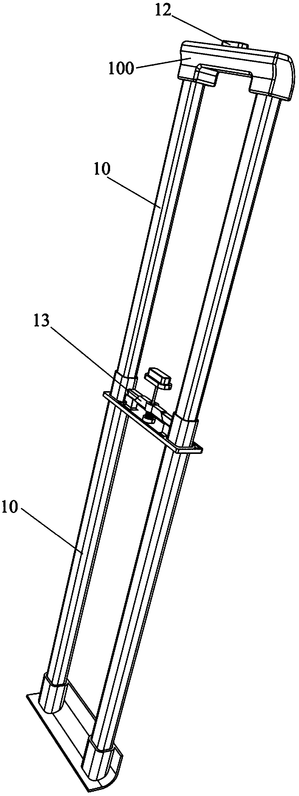
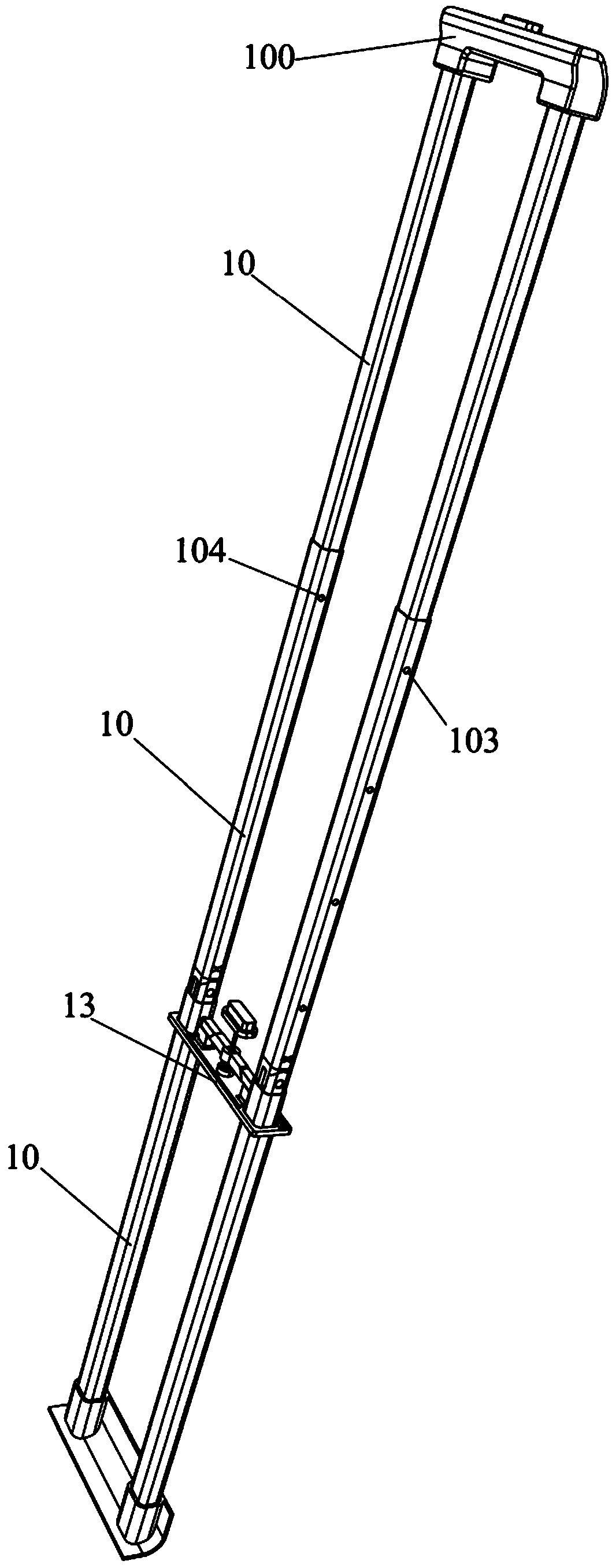
Pull rod device and trolley bag

A pull rod device and pull rod technology are applied to luggage, clothing, accessories, etc., which can solve the problems of high power consumption, inability to use rollers to move, and fatigue of the user's hands and arms, and achieve the effect of improving technical problems.

Pending Publication Date: 2019-02-05
内蒙古暗度科技有限责任公司
View PDF0 Cites 20 Cited by
  • Summary
  • Abstract
  • Description
  • Claims
  • Application Information

AI Technical Summary

Problems solved by technology

[0005] First of all, the existing trolley bags can only be moved effortlessly on a flat road surface, and cannot be moved by rollers on stairs or stairs, and can only be moved by the user on the stairs or stairs, which is laborious
[0006] Secondly, the trolley device of the existing trolley case can only expand and contract in the length direction of the trolley, which brings a lot of inconvenience to the user in the process of moving the trolley case
For example, when moving a trolley case in a vertical state of the casing, the trolley case is generally positioned at the side of the user, and the user's hands and arms stretch out sideways to hold the handle of the trolley, and the hand and arm are used during the movement. The arm provides the force to move the trolley bag forward. In this case, the user needs to spend a lot of force to move the trolley bag, and the user’s holding posture in this scene is not convenient for applying force
However, when the trolley case is moved with the box leaning towards the user, the user will bear part of the gravity of the trolley case, which will easily cause fatigue of the user's hands and arms.

Method used


Image

  • Pull rod device and trolley bag
  • Pull rod device and trolley bag
  • Pull rod device and trolley bag

Examples


Embodiment Construction

[0048] The technical solutions of the present invention will be clearly and completely described below in conjunction with the accompanying drawings. Apparently, the described embodiments are some of the embodiments of the present invention, but not all of them. Based on the embodiments of the present invention, all other embodiments obtained by persons of ordinary skill in the art without making creative efforts belong to the protection scope of the present invention.

[0049] In the description of the present invention, it should be noted that the terms "center", "upper", "lower", "left", "right", "vertical", "horizontal", "inner", "outer" etc. The indicated orientation or positional relationship is based on the orientation or positional relationship shown in the drawings, and is only for the convenience of describing the present invention and simplifying the description, rather than indicating or implying that the referred device or element must have a specific orientation, ...


PUM


Abstract

The invention provides a pull rod device and a trolley bag. The pull rod device comprises multiple levels of telescopic pipes in sequential slip connection; in at least two adjacent telescopic pipes,a sliding part capable of sliding along the inner wall of a lower-level telescopic pipe is arranged in the lower-level telescopic pipe, and the sliding part is articulated with the higher-level telescopic pipe and can be fixed at one end, connected with the higher-level telescopic pipe, of the lower-level telescopic pipe. The trolley bag comprises the pull rod device. The pull rod device not onlycan stretch and retract in the length direction, but also can deflect sidewards in the stretching and retracting process, thus the technical problem of the prior art that the pull rod device can stretch and retract only in the length direction can be improved. With the trolly bag, a user can pull the case body of the trolley bag to slide through the stairs along the steps, saving more power; whenthe trolley bag is moved on a flat road surface, the trolley bag can be put in front of or behind the user so that the user can apply power and does not get tired easily.

Description

technical field [0001] The invention relates to the field of luggage, in particular to a pull rod device and a pull rod case using the pull rod device. Background technique [0002] Trolley luggage is a commonly used luggage for people on business trips. Because the trolley bag has a pull rod and rollers, it can be pushed or pulled to move, which is relatively labor-saving, so it is widely used. [0003] During the use of the existing trolley luggage, the trolley is first pulled open, and the user holds the handle of the trolley to keep the box body of the trolley luggage in a vertical state, or make the box body tilt towards the user; then, the user It moves on a flat road, thereby driving the rollers of the trolley case to rotate, so that the trolley case moves horizontally with the user. Moreover, during the moving process, the user saves effort. [0004] But the existing trolley case has the following problems in use: [0005] First of all, the existing trolley bags ...

Claims


Application Information

Patent Timeline
IPC IPC(8): A45C5/04A45C13/26
CPCA45C5/045A45C13/262A45C2013/267
Inventor 官新钱蔡其成官乐如林子淇
Owner 内蒙古暗度科技有限责任公司
Learn More