Welding device for water turbine volutes and using method of welding device

A welding device and water turbine technology, which is applied to auxiliary devices, welding equipment, welding equipment, etc., can solve the problem of unequal accuracy in adjusting the clamping device and the turbine volute, and can only adapt to the same specification of the turbine volute and the turbine volute. , to achieve the effect of convenient limit, prevent falling off, and increase stability

Inactive Publication Date: 2019-02-05
高邮市大江泵业有限公司
View PDF6 Cites 2 Cited by
  • Summary
  • Abstract
  • Description
  • Claims
  • Application Information

AI Technical Summary

Problems solved by technology

[0004] The invention provides a hydraulic turbine volute welding device and its use method, which has the advantages of improved precision and strong applicability, and solves most of the hydraulic turbine volute welding devices. During the welding process, the hydraulic turbine volute is subjected to external force, and then The movement of the welding table caused the welding position of the turbine volute to change, resulting in incorrect welding accuracy of the turbine volute, and the welding table could not adjust the position of the clamping device and the turbine volute according to the height of the turbine volute, resulting in the failure of the clamping device It can only adapt to the problem of turbine volute of the same specification

Method used


Image

  • Welding device for water turbine volutes and using method of welding device
  • Welding device for water turbine volutes and using method of welding device
  • Welding device for water turbine volutes and using method of welding device

Examples


Embodiment Construction

[0021] The following will clearly and completely describe the technical solutions in the embodiments of the present invention with reference to the accompanying drawings in the embodiments of the present invention. Obviously, the described embodiments are only some, not all, embodiments of the present invention. Based on the embodiments of the present invention, all other embodiments obtained by persons of ordinary skill in the art without making creative efforts belong to the protection scope of the present invention.

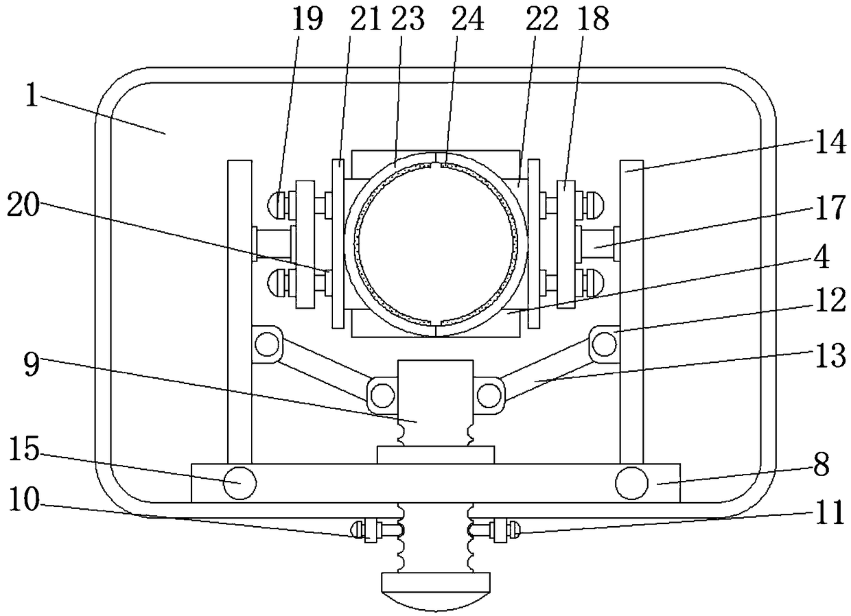
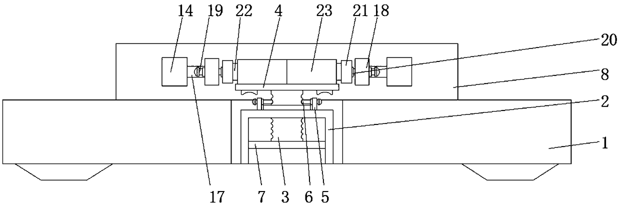
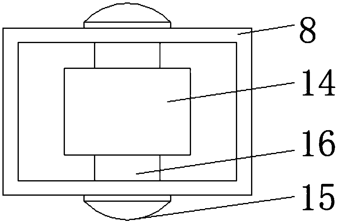
[0022] see Figure 1-3 , a hydraulic turbine volute welding device, including a welding table 1, the inner surface of the welding table 1 is fixedly connected with a positioning cylinder 2, through the role of the positioning cylinder 2, the stability of the positioning rod 3 when moving is increased, and the positioning rod 3 is avoided. Shake back and forth when moving, causing the bearing plate 4 to shake back and forth, causing the volute to move, reducing...


PUM


Abstract

The invention relates to the technical field of welding devices, and discloses a welding device for water turbine volutes. The welding device comprises a welding table. A positioning cylinder is fixedly connected to the inner surface of the welding table. A positioning rod is slidably connected to the middle of the positioning cylinder. One end of the positioning rod is fixedly connected with a bearing plate located above the positioning cylinder. The top of the positioning cylinder is fixedly connected with horizontal plates located on the two sides of the positioning rod. The side faces of the horizontal plates are movably connected with the horizontal plates. According to the welding device for the water turbine volutes and the using method of the welding device, under the effect of thepositioning cylinder, the moving stability of the positioning rod is improved, and the situation that the bearing plate shakes back and forth due to back-and-forth shaking of the positioning rod in the moving process, and consequentially the welding precision is reduced is avoided; and under the effect of the horizontal rods, the positioning rod is directly fixed after being moved, so that the situation that the bearing plate drives the positioning rod to slide downwards automatically under the effect of the gravity is prevented, and then the volute slides downwards automatically and cannot be welded is prevented.

Description

technical field [0001] The invention relates to the technical field of welding devices, in particular to a hydraulic turbine volute welding device and a method for using the same. Background technique [0002] The volute is the abbreviation of the volute-type water diversion chamber. Its shape is very similar to a snail shell, so it is usually referred to as the volute. In order to ensure uniform water supply to the water guide mechanism, the section of the volute is gradually reduced. The necessary circulation is formed to reduce the working intensity of the water guiding mechanism. [0003] The volute of the turbine is welded by multiple parts. Most of the existing welding devices for the volute of the water turbine. During the welding process, the volute of the water turbine is subjected to external force, and then moves on the welding table, causing the welding position of the volute of the turbine to occur. The change caused the accuracy of the welding of the turbine v...

Claims


Application Information

Patent Timeline
Patent Type & Authority Applications(China)
IPC IPC(8): B23K37/04B23K31/02
CPCB23K31/02B23K37/04
Inventor 徐祝山徐鹏程
Owner 高邮市大江泵业有限公司
Why Eureka
Try Eureka